PIC microcontroller's 4 & 215; 4 determinant keyboard works
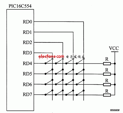
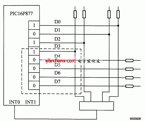
How a 4×4 matrix keyboard works with a PIC microcontroller: (1) The principle of the single-chip microcontroller's keyboard system The connection of a matrix keyboard is more complex than that of an independent keyboard, and the programming implementation is also more challenging. However, compared to the independent keyboard, the matrix keyboard can support more keys while using the same number of I/O ports. The schematic diagram is shown in Figure 1. Figure 1: Schematic of a 4×4 matrix keyboard In practical applications, the PIC16C5X, a universal programmable keyboard and display interface device, can be used for both keyboard input and display control. This single-chip device allows for efficient operation of a matrix keyboard with up to 64 buttons. It continuously scans the keyboard, automatically debounces, identifies the pressed key, and provides the corresponding code. It also supports double-key or multi-key press detection. In the display section, it provides a scan-enabled interface for LEDs and fluorescent displays, capable of displaying up to 16 characters or numbers through multiplexing. To determine if a key is pressed, the column lines are set to low, and the row lines are read. If any row line is pulled low, it indicates a key press. The method involves setting all column lines to low and reading the row lines into the accumulator. If not all rows are high, a key is pressed. To identify which key is pressed, the column lines are set to low one by one, and the row lines are checked. If a row line is low, the key at the intersection of that row and column is the one pressed. (2) Scanning method for single-chip keyboards The scanning method involves checking each row (or column) in sequence after detecting a key press. If a row (or column) is not all high, the key is located at the intersection of the row and column where the low level occurs. This method uses a row-by-row (or column-by-column) scan query. In this case, pull-up resistors are connected to the row or column lines. The matrix keyboard scanning program uses this method to determine which key is pressed. In Figure 1, the row and column lines are connected to +5V, and the columns are scanned sequentially. 1. Progressive (or column) scanning method To identify which key on the matrix keyboard is pressed, the progressive scanning method is one of the most commonly used techniques. The process includes: - First, check if any key is pressed by setting all row lines (Y0 to Y3) to low and checking the column lines. If any column line is low, a key is pressed. Otherwise, no key is pressed. - Once a key is detected, the specific key position is determined by setting one row line to low at a time and checking the column lines. When a column line is low, the key at the intersection of the low row and low column is the pressed key. 2. Inversion method The inversion method is faster than the scanning method. Instead of scanning multiple times, it only takes two steps to detect the key. The principle is shown in Figure 2. Figure 2: Principle of line inversion The hardware in the figure operates in interrupt mode and uses an 8-bit I/O port to form a 4×4 keyboard. Assuming the broken line in the figure represents the pressed key, the steps are as follows: - Set D3–D0 as column input lines and D7–D4 as row output lines. Set the output signals D7–D4 to 0000. If a key is pressed, the AND gate output goes low, triggering an interrupt to the CPU, indicating a key press. The data from D3–D0 is stored in a memory unit, with the 0 bit representing the column position. - Reverse the direction: set D7–D4 as input lines and D3–D0 as output lines. Output the data from the N unit (the column position) and read the I/O data, storing it in the N+1 unit. The D7–D4 bits that are low represent the row position. Finally, combining D3–D0 from the N unit and D7–D4 from the N+1 unit gives the key value. Conclusion: In MCU application systems, any I/O port or extended I/O port can be used to create a matrix keyboard. Since the display system often includes a display, the keyboard and display circuits are usually combined in a single interface to save I/O lines.

Poles For Electric,Power Transmission Pole,35Kv Electric Steel Pole
JIANGSU XINJINLEI STEEL INDUSTRY CO.,LTD , https://www.chinasteelpole.com