PIC microcontroller's 4 & 215; 4 determinant keyboard works
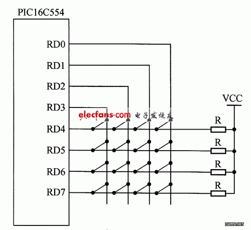
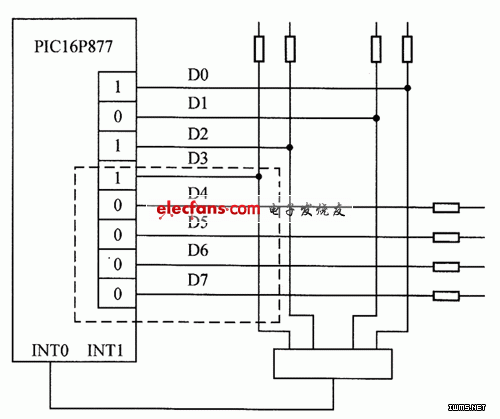
How a 4×4 matrix keyboard works with a PIC microcontroller: (1) The principle of the single-chip microcontroller's keyboard system Compared to an independent keyboard, a matrix keyboard has a more complex wiring structure and requires more complicated programming. However, it allows for more keys to be connected using the same number of I/O ports. The schematic diagram is shown in Figure 1. Figure 1: Schematic of a 4×4 matrix keyboard In practical applications, devices like the PIC16C5X can be used as a programmable interface for both keyboard input and display control. This single-chip device supports matrix keyboards with up to 64 keys, offering continuous scanning, automatic debouncing, key recognition, and protection against multiple key presses simultaneously. In the display section, it provides a scan-enabled interface for LED or fluorescent displays, supporting up to 16 characters or numbers through multiplexed signals. To detect a key press, the column lines are set to low, and the row lines are read. If any row line is pulled low, it indicates that a key is pressed. The exact key can be determined by sequentially setting each column to low and checking the row states. (2) Single-chip keyboard scanning method The scanning method involves checking each row or column in sequence after confirming a key press. If a row or column is not all high, the key is located at the intersection of the low row and column. This process is repeated for accurate detection. The scanning method typically uses pull-up resistors on the rows or columns, ensuring that only one line is active at a time. In Figure 1, the rows and columns are connected to +5V, and the columns are scanned one by one. 1. Progressive (or column) scan query method This is one of the most commonly used methods for identifying a key press. The process includes: 2. Inversion method This method reduces the number of scans needed to identify a key. It works in two steps, as shown in Figure 2. Figure 2: Principle of line inversion The hardware operates in interrupt mode, using an 8-bit I/O port to form a 4×4 keyboard. Suppose the key in the diagram is pressed. The inversion method proceeds as follows: Conclusion: In MCU systems, any I/O port or extended I/O port can be used to create a matrix keyboard. Since such systems often include a display, it's common to integrate the display and keyboard into a single interface circuit to save I/O resources. This approach improves efficiency and simplifies design. Lighting Pole,Steel Lamp Pole,Street Light Poles,Garden Lamp Post JIANGSU XINJINLEI STEEL INDUSTRY CO.,LTD , https://www.chinasteelpole.com


