Detailed medical sterilizer control system
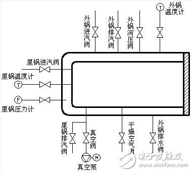
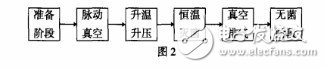
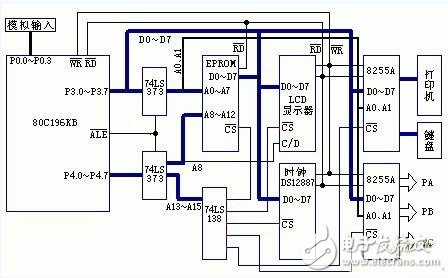
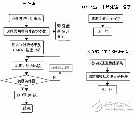
Sterilizers are important equipment for protecting human life and health. Both domestic and commercial sterilizers are popular in developed countries. The sterilizer sterilization depends largely on whether the control system is reliable, for a medical device plant sterilizer control system instability, man-machine interface and other practical problems, the author uses 80C196KB microcontroller design sterilization control for the plant The system eliminates the defects of the original system and adds some functions accordingly. Compared with 51 series single-chip microcomputers, the 96 series on-chip resources are more abundant and the design of the system is relatively easy. The sterilizer is mainly used to sterilize five types of packaging, equipment, latex, liquids, and other types. The process is generally the same, and the differences can be controlled by the program. According to its working principle (Fig. 1), it can be seen that various operation controls are performed according to whether the temperature and pressure of the inner and outer pans reach a predetermined value. A total of 4 analog input: external pot temperature TW, external pot pressure PW, pot temperature TL, pot pressure PL; control output a total of 16: the outer pot steam valve switch IW, the outer pot steam valve switch OW, Liguo steam inlet valve switch IL, Liguo steam exhaust valve switch OL, vacuum valve switch ZK, dry air valve switch GZ, oil pump relay off YB, vacuum pump relay off ZB, electromagnetic hydraulic valve (high pressure valve GF, rack valve CF, latch valve MF), signal indication (power indication PowerL, total power indication PowerZ, fault indication ERR, buzzer alarm ALarm). Figure 1 working principle The figure shows that the main body of the sterilizer is a high-pressure vessel with a jacket and a sealed door. It is equipped with vacuum pumps, vacuum valves, steam valves and other control devices and temperature and pressure sensors. The working process is shown in Figure 2. The hardware structure of the control system is shown in Figure 3 below: Figure 3 Control System Hardware Structure The actual temperature and pressure in the sterilization chamber are measured by the AD590JH integrated semiconductor temperature sensor and the MPX5500D integrated pressure sensor. The collected 2-way temperature signals and 2-way pressure signals are sent from P0.0 to P0.3 to the 80C196CKB chip. In the 80C196CKB, there is an 8-channel 10-bit A/D converter for multi-channel data acquisition systems. One A/D conversion requires 88 state cycles (22 μs with a 12 MHz crystal). The advantage is that the hardware circuit is greatly simplified when the process requirements are satisfied, which is beneficial to the reliability of the circuit. The digital quantity in the 80C196CKB is digitally filtered and scaled and then displayed on the LCD. On the other hand, compared with the setting, the deviation E and deviation rate EC are obtained, which provides the basis for follow-up control. The parallel output interface circuit 8255A is used to realize the output control of nearly 20 switching control quantities. The temperature control is achieved by adjusting the opening of the steam valve. The control volume is converted to an analog output via D/A, and the steam valve opening is controlled after power amplification. The user sets the sterilization temperature, time and pulsating vacuum through the keyboard to meet various disinfection requirements. Using DS12887 Parallel Clock Module The man-machine interface mainly includes a keyboard, a display, and a micro-printer interface circuit. The keyboard is in the form of a soft keyboard, which is processed by the program to identify, debounce, and confirm the key code. The hardware interface of the keyboard and printer is realized through a 8255A. The display uses an LCD display module with a built-in T6963C controller (connected directly to the CPU) for dynamic display of temperature, pressure, time, and operational cues. The printer is used to print the relevant operating process parameters. The implementation of the user interface in software is achieved by software modules that are distributed rather than centralized. All devices of this system are powered by a single +5V power supply. Due to practical application, the signal is susceptible to interference during data acquisition. Therefore, an optocoupler isolation circuit is adopted at the signal input/output contact point, and measures such as shielding resistance are used to ensure the stability of the system. This system has a lot of functions. For the convenience of design and maintenance, a structured module design method is used, which is progressively detailed from top to bottom. Subroutines with independent functions are all set as subroutine modules. The related functions are all related to the function subroutines. achieve. The main program consists of initialization, sterilizing category selection and related display, parameter comparison, actuator output control, etc. The core is the comparison of temperature and pressure parameters and the corresponding output control; the dynamic display of time is the timer 1 overflow interrupt handler. Execution; 4 channels of temperature, pressure data acquisition processing and dynamic display completed by the A/D conversion end interrupt handler. Because the display program is relatively large, running on the interrupt handler makes the background program concise, which is beneficial to the reliability of the software operation. The program flow is shown in Figure 4. Figure 4 program flow chart The basic process of program operation is: After initialization, A/D conversion is started to collect temperature and pressure signals. After processing, these data are compared with the user-defined operating parameters, and then the different actions of the system actuator are determined to meet the operation parameters. Within the scope of process requirements. The software of this control system is all in assembly language, which has high execution efficiency and reliable operation. It is limited by space limitations and is not introduced one by one. This is a practical embedded control system with 80C196KB as its core. Its functions are complete and the design is relatively simple. The actual application shows that the entire system runs smoothly and the sterilization control is reliable. Compared with the sterilization control system based on PLC with the same function, its cost is low, the man-machine interface is friendly, the operation is easier, and it has good promotion value. Stainless Steel Pipe,Medical Ss Capillary Pipe,Stainless Steel Tubes,Seamless Presion Stainless Steel Tube ShenZhen Haofa Metal Precision Parts Technology Co., Ltd. , https://www.haofametal.com