Detailed content about embedded FPGA
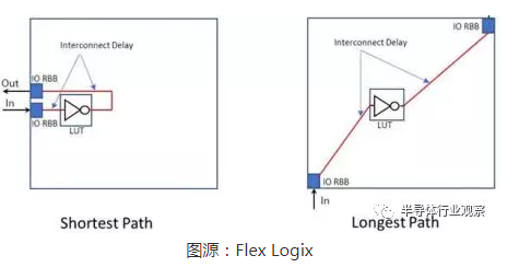
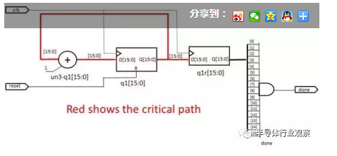
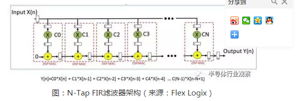
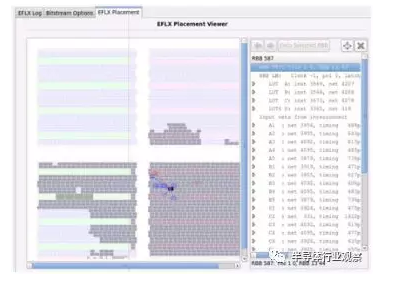
Embedded FPGA (eFPGA) refers to embedding one or more FPGAs in ASIC, ASSP or SoC chips in the form of IP. In other words, eFPGA is a digitally reconfigurable structure composed of programmable logic in a programmable interconnect, usually represented as a rectangular array, with data input and output located around the edge. eFPGA usually has hundreds or thousands of inputs and outputs, which can be connected to the bus, data path, control path, GPIO, PHY or any required device. All eFPGAs use a look-up table (LUT) as a basic building block. The LUT has N inputs to select a small table whose output represents any required Boolean function of N inputs. Some eFPGA LUTs have four inputs, and some have six. Some LUTs have two outputs. LUTs usually have flip-flops at the output; these can be used to store results. These LUT register combinations usually appear in quaternary form, as well as carry arithmetic and shifters to effectively implement adders. The LUT receives all inputs from the programmable interconnection network and feeds back all outputs to the programmable interconnection network. In addition to the LUT, eFPGA may also contain MAC (multiplier / accumulator module). They are also connected to programmable interconnect networks to provide more efficient digital signal processing (DSP) and artificial intelligence (AI) functions. For memory, there is a lot of RAM, usually a two-port package. As for the LUT and MAC, they are connected to the programmable interconnect network via RAM. The eFPGA has an outer ring of input and output pins that connect the eFPGA to other parts of the SoC. These pins are also connected to a programmable interconnect network. Software tools are used to synthesize Verilog or VHDL code to program eFPGA logic and interconnects to achieve any desired function. eFPGA is a convenient new logic block that can increase the value of SoC in many ways, including: Extensive and fast control logic using hundreds of LUTs; Reconfigurable network protocol; Reconfigurable algorithms for vision or artificial intelligence; Reconfigurable DSP for aerospace applications; Reconfigurable accelerator for MCU and SoC. In addition to the above, there are many more, not introduced here one by one. Today, there are already some eFPGA suppliers, including Achronix, Flex Logix, Menta and QuickLogic, in addition, there are some smaller suppliers. With these options, customers need to decide which one best meets their needs. So, how to choose? Although commercial factors need to be considered, this article focuses on technical factors. Step 1: Process compatibility Usually, even in the early stages of IP evaluation, companies will choose foundry plants and process nodes. TSMC, GlobalFoundries and SMIC are now or are developing eFPGAs for process nodes including 65nm, 40nm, 28nm, 22nm, 16nm, 14nm and 7nm. However, not all suppliers have eFPGA for all foundries / process nodes, at least not yet. It is important to check through their website which are compatible with your process. You should also see if the eFPGA in question has been verified in the chip and provide a report under NDA. Don't forget to check the compatibility of the metal stack. The key IP you choose, such as SerDes or your application, may require you to use a specific metal stack, but not all eFPGA IPs are compatible with all metal stacks. Step 2: Array size and function Not all eFPGA vendors can make very small-scale eFPGAs, and at the same time, not all vendors can make very large-scale eFPGAs. In addition, the nature of the MAC and RAM they support may vary. Whether you need hundreds of LUTs or hundreds of thousands of LUTs, and your needs for MAC and RAM, this may filter out some suppliers. Step 3: Use RTL for benchmarking eFPGA vendors will provide you with evaluation software so that you can determine (RTL) the silicon area and performance that each eFPGA can achieve. You need the eFPGA to be able to operate in the same temperature and voltage range as the rest of the SoC, so make sure that what you need is supported. When benchmarking, it is important to compare apples to apples (compare apples to apples). For example, you should compare each eFPGA on the same process (slow / slow or typ / typ or fast / fast), the same voltage and the same temperature. You should expect that software tools from eFPGA vendors will allow you to check performance at different process corners and voltage combinations. Please note that your RTL is for eFPGA. If RTL is used in a hard-wired ASIC design, there will often be 20 to 30 logic layers between flip-flops. If you put it in a non-optimized eFPGA, it will run very slowly. In eFPGA, LUT output always has triggers, you can use them to add more pipelines to RTL to get higher performance in eFPGA. When it comes to RTL, making sure what you are testing is important to you. A 16-bit adder. What you care about is how fast it runs, but if you are not careful, the results you see may surprise you. Now imagine a big eFPGA. If the adder is placed in a corner of the array and the input and output are close, the performance will be much higher than if the adder is found in the middle of the array. This is because if you observe the performance from the array input to the array output, when the adder is in the middle of the array, the distance from the data input to the adder of the adder output will be longer. In fact, the adder is the same and runs fast in both positions. The problem is that your test does not isolate the performance of the adder, but it also adds the signals needed to reach the adder. The following figure is an example. It uses a LUT for wiring. The LUT speed will not change, but the delay in entering and leaving the LUT through the interconnect will occur. To cope with this effect, especially because you may compare two eFPGAs of different sizes, all you need to do is set up registers on the input and output, which ensures that the performance you care about can be measured regardless of the size of the array and Location restrictions. If you need the DSP or AI function of MAC, please understand the difference between the multiplier size and pipeline of each eFPGA. If RTL specifies an MxN multiplier, the synthesis software will ensure that the eFPGA implements it, but it may span two or more multipliers to achieve the desired effect. If you need MxN, then this is very important. However, if you try to compare the multiplier performance of apples-to-apples, you will want RTL to use a multiplier size suitable for all eFPGAs you are evaluating. Some eFPGAs bring MACs together directly, which is much faster than programmable interconnect networks. Implementing the N-Tap FIR filter will show the difference between eFPGA with MAC-to-MAC pipeline and eFPGA without pipeline. The figure above shows an example of an N-Tap FIR filter implemented using pipelined DSP MAC. Step 4: Use the RTL benchmark area you need As with performance, be very careful when trying to benchmark relative areas of different eFPGA RTLs. Some eFPGA vendors allow you to easily generate dozens of different array sizes, but others may only provide two sizes for your benchmark. The first step is to view the LUT count (or MAC count). However, different eFPGA vendors may have different LUT sizes. It may not fill up in the lookup table, so if you have two triggers to enter one NAND gate, and then enter another trigger, then any size of the lookup table will implement a NAND gate. Some eFPGAs have two flip-flops at the output, which allows the N-input LUT to be decomposed into two smaller LUTs that share the N-input LUT and some input subsets. This function can improve area utilization. Even if you are benchmarking N-LUT eFPGAs from two vendors-and your design uses half of the two LUTs and the area of ​​the two is the same-you cannot conclude that they are equally good. What you need to determine is whether the utilization rate of eFPGA LUT can be achieved. Generally, the utilization rate of eFPGA is 60-70%, but the utilization rate of some eFPGA can reach 90%. The only way to find it is to make the RTL almost fill the eUT's LUT. Another way to gain a sense of usage is to view the visualization of the placement. In the following example, LUTs are obviously very tightly grouped together (shaded blocks are the LUTs used in the design), which is a good visual indication of high utilization. However, you must be careful even here. If in the above design, the input and output are evenly distributed on the edge of the eFPGA array, then as the location / path software minimizes the critical path, it will have the effect of distributing the LUT more evenly. Therefore, when using this visual inspection, try to group the input and output into a corner of the eFPGA so that the location / routing software can put the LUT together to minimize the critical path. Step 5: Benchmark input and output capacity Some eFPGA-based applications require a lot of input and output. For example, the bus of a network chip can be 512 bits wide (sometimes even thousands of bits wide). You need to check the input and output counts available for each K-LUT to see if it is within the range that meets your needs. in conclusion eFPGA is an exciting new tool that allows SoC architects to make their chips more flexible and reconfigurable. Using the above guidelines, you will be able to find the eFPGA that best suits your unique application and specific needs more quickly. If you choose the right solution, you will be able to realize the full potential of eFPGA. Shenzhen Hengstar Technology Co., Ltd. , https://www.angeltondal.com