A detailed explanation of the negative temperature coefficient thermistor
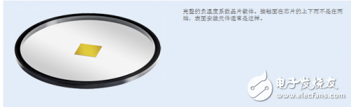
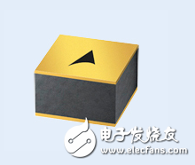
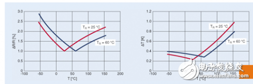
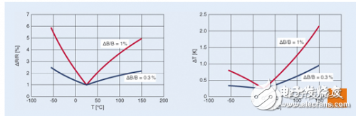
The new EPCOS negative temperature coefficient thermistor was developed by TDK-EPC in a chip-based manufacturing process and can be easily integrated into power semiconductor components. Allows reliable temperature monitoring to be performed to protect expensive electronic equipment from malfunction or damage. Traditional ceramic NTC (negative temperature coefficient) thermistors are ideal for temperature measurement and are also cost effective components. EPCOS has manufactured these products for many years, with leaded models or surface mount components of the most common EIA package sizes, such as 0402, 0603, 0805, and so on. Negative temperature coefficient thermistors are used for a wide range of applications in automotive and industrial electronics and home appliances such as refrigerators, washing machines, dishwashers, and cookers. These miniature surface mount models of negative temperature coefficient thermistors are increasingly integrated directly into power semiconductor components such as IGBT components for over-temperature protection. However, traditional models can create certain difficulties in process management. Including: The terminals must be designed as pads on the semiconductor substrate for soldering or wiring. If the component is not completely flat, the thermal resistance between the substrate and the negative temperature coefficient thermistor increases. Different temperature coefficients of the substrate and negative temperature coefficient thermistors may cause breakage. Thermal and mechanical stresses that arise from the semiconductor injection molding process can also cause the thermistor to crack. Using complex, costly technical processes can solve some of the problems. However, the risk of breakage during semiconductor operation cannot be completely avoided. To solve these problems, TDK-EPC developed a chip-based manufacturing process for EPCOS chip negative temperature coefficient thermistors (Figure 1). Figure 1: Negative temperature coefficient thermistor chip before separation Complete negative temperature coefficient chip carrier. The contact surface is on the top and bottom of the chip instead of at both ends, as is the case for surface mount components. For negative temperature coefficient thermistors made from chips (Figure 2), the electrical terminal configuration is very important: unlike traditional mounting components, they are located on the top and bottom of the surface rather than on both sides of the component. This can be directly connected horizontally to the semiconductor via the lower terminals. The upper terminals are contacted by a common wire bond. This contact surface is gold plated or silver plated to achieve the best solder wire results. The horizontally arranged terminals on the substrate significantly reduce the risk of crushing and also make welding unnecessary. Figure 2: Negative temperature coefficient thermistor chip The placement of terminals in the upper component greatly reduces the risk of breakage. Chip Processing Allows Smaller Tolerances Another advantage of negative temperature coefficient chip thermistors is their smaller electrical and thermal tolerances. This accuracy is obtained by special technical processes: Before the separation of components, the total resistance of the chip is determined by the rated temperature of 100 °C. The size of the thermistor that is separated is calculated from this, thus ensuring that the tolerance specifications of the individual components are very precise. Figure 3 shows the resistance and temperature enthalpy at the rated temperature of 25-60 °C. Figure 3: Resistance and Temperature Tolerance The EPCOS negative temperature coefficient chip thermistor's resistance (left) and temperature (right) tolerances are based on the rated temperature of 25-60°C. Reduced tolerances and the resulting high precision go beyond the requirements of semiconductor manufacturers. This allows the IGBT to operate at temperatures very close to the maximum allowable value. The B value of the negative temperature coefficient thermistor and its tolerance are very important for its precision. In general, the B value determines the slope of the resistance/temperature curve. This relationship is very obvious in Figure 4, showing how the resistance and temperature change as a function of different B-value tolerances. Figure 4: Resistance and temperature tolerance as a function of B value The narrower the B-value tolerance, the more accurate the measured value. The graph shows the ΔB/B worth resistance (left) and temperature (right) tolerances at 0.3% and 1%. Figure 5 shows the effect of B value on measurement accuracy. This figure will be rated at 25 °C (3% B tolerance; 5% tolerance at R2525) Package size 0603 Traditional surface-mount negative temperature coefficient thermistor with 100 °C (1% of B capacity Poor; 3.5% tolerance at R25100) Comparison of rated temperature negative temperature coefficient thermistor chips. Obviously, the chip negative temperature coefficient thermistors provide significantly narrower and thus better tolerances. Figure 5: Comparison of Chip Negative Temperature Coefficient Thermistor and Traditional Surface Mount Negative Temperature Coefficient Thermistor The temperature around 120 °C is very important for semiconductors. The chip-type negative temperature coefficient thermistor has a high measurement accuracy of ±1.5 K here, and the surface mount component can only achieve ±5 K. In fact, this means that IGBT modules with negative temperature coefficient thermistors must be derated at the 120 °C measurement temperature because the actual temperature may already reach 125 °C, taking into account the ±5 K tolerance. Temperature is very dangerous for the depletion layer. On the other hand, the temperature may only be 115 °C, but in spite of this, it is necessary to cut off electricity. The same must be considered is due to the welding process, most of the surface of the negative temperature coefficient of hot surface resistance of up to ± 3% resistance drift, further reducing the measurement accuracy. The situation for the chip negative temperature coefficient thermistor is completely different: Since there is only a narrow tolerance of ±1.5 K at 120 °C, there is no need to power down until the temperature reaches 123 °C. This example clearly shows that the chip's negative temperature coefficient thermistor allows the use of IGBT components to achieve the highest performance limits and can therefore be better utilized. Today's existing chip negative temperature thermistors can operate at temperatures up to 155 °C. The maximum operating temperature can even reach 175 °C. At the same time, the B value tolerance can be reduced to 0.5%. This also makes the chip negative temperature coefficient thermistor perfectly suitable for a new generation of semiconductors based on silicon carbide (SiC), for example.
Barrier Terminal Block
Terminal blocks are used to facilitate the connection of wires. In fact, they are a piece of metal sheet sealed in insulating plastic. There are holes at both ends to insert wires and screws to fasten or loosen them. For example, two wires sometimes need to be connected and sometimes need to be disconnected. At this time, they can be connected with terminals and can be disconnected at any time without having to connect them It's very convenient and fast to weld or wind together. And it is suitable for a large number of wire interconnection. In the power industry, there are special terminal blocks, terminal boxes, all of which are terminal blocks, single-layer, double-layer, current, voltage, common, breakable, etc. A certain crimping area is to ensure reliable contact and enough current.
Barrier Terminal Block ShenZhen Antenk Electronics Co,Ltd , https://www.antenkcon.com