Composition of Forward Power Design by RCD of UC3845
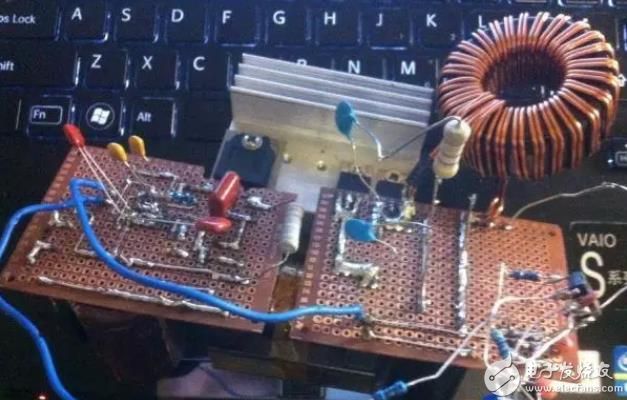
Circuit design has always been thinking about the goal of low loss and high efficiency. Developers can minimize the loss through the cooperation of devices and circuits in the design of the transition. The UC3845 allows designers to use only the fewest external components to achieve the most profitable solution. This is the component choice, and the RCD circuit's biggest role in power supply design is to absorb the resistors, thereby minimizing losses. This article will give you a summary of the forward power supply design made up of the UC3845 RCD. Hopefully it will help everyone. Only consider the current loop in the circuit, the voltage is open loop, so the no-load voltage is equal to the input voltage divided by the turns ratio, and has nothing to do with the duty cycle, to calculate the impact of leakage inductance spike, the actual measurement input 234VAC output no load 100V DC. This voltage fully satisfies the needs of the Xenon lamp triggering. In order to ensure the safety of the capacitor voltage at high commercial power, a capacitor of 160V was chosen so that the voltage was sufficient. The 50KHz switching loss is not too large for the frequency trade-off, and the core does not have to use a large amount to output power. On the other hand, the number of primary turns is large, and the magnetic flux density shift is small, and the design is conservative. Figure 1 is the final circuit diagram with precise parameters. The question mark component is not actually installed. At first glance, this circuit does not seem to have anything special. However, the details determine the success or failure of the entire production. The following questions and solutions for design and production are discussed. Is the auxiliary winding in the forward or flyback form? When the auxiliary winding is forward excited, peak rectification is generally used so that the duty cycle is greater than zero. The auxiliary power supply voltage is always related to the number of turns of the DC high voltage in the previous stage. When the auxiliary winding uses flyback, the voltage variation varies greatly with the duty cycle and load, and there may be a problem of non-startup. Since the input voltage here is 180-260V, the auxiliary voltage change is 13-20V, IC and MOS are acceptable. The actual results are also more consistent, but a little higher than expected. Although it also changes with load changes, the changes are small, and basically do not affect the struggle for production. It should be noted that if the scheme with APFC is adopted, it is strongly recommended that the forward auxiliary supply voltage should be more stable. How to reset The forward transformer has no reset capability and requires passive reset to function properly. Common solutions include reset winding reset, RCD reset, LCD reset, active clamp reset, and resonant reset. The reset of the reset winding will increase the complexity of the transformer, and put forward higher requirements for the transformer's withstand voltage, and the duty cycle cannot be greater than 50. RCD reset is relatively simple, the duty cycle can also be greater than 50, the switch voltage stress is relatively low. However, all excitation energy and leakage inductance energy are consumed by the resistor. Efficiency will be a little worse. Active clamping requires a special IC, although it can achieve maximum efficiency. The duty cycle can also be greater than 50 but adds cost and complexity. Resonance reset increases the voltage or current stress of the switch, regardless of the synthesis, the RCD reset was eventually selected, but the duty cycle was not designed to be greater than 50. Transformer should not add breath Forward transformers do not theoretically require energy storage, so theoretically no atmosphere is required. At the beginning, there was no open-loop breath test. The core had a suction sound when it was turned on, but a 300W load was added and it worked well without any sound. Then there was a problem in the closed loop. After the closed loop, it was found that it was capable of constant current and accuracy was enough, but the transformer was also heating up. Looking at the waveforms with an oscilloscope is working intermittently and thinks about the feedback loop. After the repair, the duty cycle is continuous, but there is still jitter, and the transformer still emits heat. At this time, the transformer saturation was further thought out, and the waveform on the sampling resistor was more certain of his own point of view. In the messy waveform, it can be seen faintly that the winding current rises sharply after certain cycles, which is a sign of saturation. Afterwards, a 0.08-mm-thick sheet of paper was placed around the core, adding a breath. At the same time the C109 from the electrolytic 400V4.7uF replaced by CBB400V0.1uF decisively, and the problem of transformer thief heat is also resolved. It was later guessed that the transformer primary has 46mH inductance. Causes the reset current to be too low, and the addition of a breath reduces the primary inductance. It also reduces remanence, although the reset resistance is a bit hotter than it was before. But the transformer can work reliably is the focus. It can be seen that increasing the atmosphere has a positive effect on improving the saturation resistance of the transformer. Misunderstanding of UC384x and current mode The third leg of the UC384x is a current feedback pin. Everyone knows that current feedback can be used for protection. In fact, this pin also plays a more important role. That is PWM modulation, which acts like a sawtooth wave from an oscillator in a voltage-mode PWM, which is ignored by many. Often see someone ask why the UC384x's 3-pin ground duty cycle has always been the maximum 1 and 2 feet can not control the duty cycle It should be understandable now that the output of the error amplifier controlled by pin 1 and pin 2 after the pin is grounded is always greater than the pin 3 voltage, and there is no chance of reducing the duty cycle. Therefore, the waveform of pin 3 of UC384x is related to whether the entire power supply can work normally. What is the slope compensation compensation? Why slope compensation? When does compensation need to be made? This estimate is annoying for many beginners. It is the effect of the capacitance between pins 3-4. The slope compensation is the slope of the voltage change of pin 3 of the UC384x pin. Why compensation? When does compensation need to be made? Compensation is required when the slope of the 3 feet is insufficient, because a small slope of the 3 foot causes a very large adjustment of the feedback voltage to make a very large adjustment and lead to a blowout. Normally, the DCM's flyback does not need to be compensated, because the voltage slope of the 3 pin is proportional to the slope of the primary current and should be relatively large. The CCM's flyback and forward (single/double counting) and even CCM's Boost are needed. Because the current primary current change is small when the tube is conducting (although the cause is not the same, but the expression is similar), the slope of the 3 foot change is small and it is easy to extract the wind. In this case, the slope compensation is needed. Therefore, it is necessary for forward slope compensation! The previously mentioned slamming to explosion is caused by no slope compensation. The figure below is the final product, but it has not yet been installed on the PCB, but it has basically taken shape. Finally, in fact, the usefulness of this power supply is very large, as long as make some adjustments can become a constant current limiting high-power battery charger, or LED drive power supply, etc., there is a problem that part of the reset resistor heat is more serious, this can be Through the heat sink to solve. Multi-Port Usb Charger,5V2A Usb Charger,Mobile Phone Charger,Multi Ports Usb-A Charging Hub shenzhen ns-idae technology co.,ltd , https://www.best-charger.com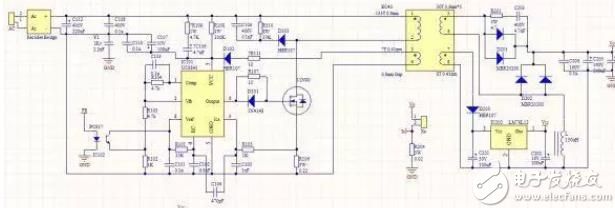
The LCD reset is slightly better than RCD and can perform essentially lossless absorption, returning energy to the high voltage capacitor. However, fewer articles were introduced than they were.