Design Scheme of Vector Control System of AC Asynchronous Motor
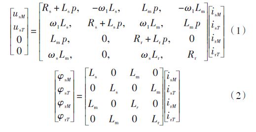
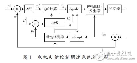
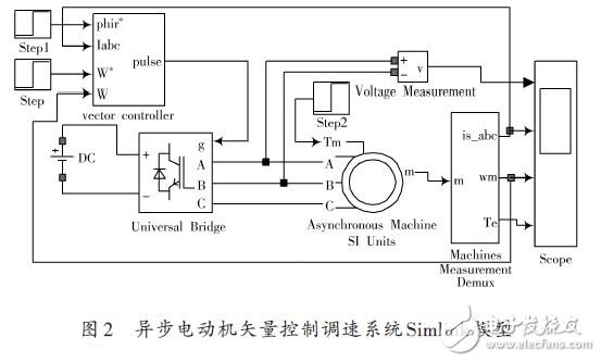
0 Preface The dynamic mathematical model of asynchronous motor is a high-order, non-linear, strongly coupled multivariable system. Vector control is an advanced control method of motor control system. Due to its superiority in AC speed regulation, it is widely used in asynchronous motor Speed ​​system. Simulink-based AC asynchronous motor simulation can verify the effectiveness of the system design scheme, and may encounter system design difficulties in the laboratory application process. This paper takes the double closed-loop vector control system as the research object, and performs simulation in Simu-link to verify the effectiveness of the control system. By analyzing the simulation results, the dynamic and static characteristics of the vector control system are obtained, thus confirming the feasibility of this design. 1 Vector control principle Vector control system, abbreviated as VC system, coordinate transformation is the core idea. The basic idea of ​​vector control is to generate the same rotating magnetomotive force as the criterion. The stator AC current of the asynchronous motor on the static three-phase coordinate system is equivalent to the AC current on the two-phase static coordinate system. It is equivalent to the DC current on the synchronous rotating coordinate system. In the equivalent process, the decoupling control of magnetic flux and torque is achieved to achieve the control effect of the DC motor and the control amount of the DC motor. The three-phase asynchronous motor can be equivalently controlled by a DC motor to obtain dynamic and static performance close to the DC speed regulation system. The vector transformation in vector control includes three-phase to two-phase transformation and synchronous rotation transformation. The direction of d axis along the rotor total flux vector φr is called M axis, and the q axis is rotated counterclockwise by 90 °, that is The direction is called the T axis, and the voltage-current equation is rewritten as formula (1), and the flux linkage equation is formula (2): The torque equation can be simplified as: According to equation (2), the rotor flux φr is only generated by the stator current excitation component isM, and has nothing to do with the torque component isT, and isM and isT are perpendicular to each other, and the two are decoupled. The structure of the vector control variable frequency speed regulation system is shown in Figure 1. It can be seen from Figure 1 that the system uses closed-loop control of speed and flux linkage. The amount marked with * in the figure is a given amount, and the rest are actual measured values. 2 Simulink-based simulation model of asynchronous motor vector control system 2.1 Overall system model According to the principle of vector control system, the electrical system toolbox SimPowerSystems in Matlab / Simlink software is used to simulate the system. The simulation model of the overall system is shown in Figure 2. Modern Decorative Ceiling Fans,Modern Decorative Ceiling Fan,Home Modern Ceiling Fans,Modern Ceiling Fans With Remote Jiangmen MagicPower Electrical Appliances Co.,Ltd. , https://www.magicpowerfan.com