Using the new pulse level modulation technology to improve the luminous efficiency of high-brightness LED
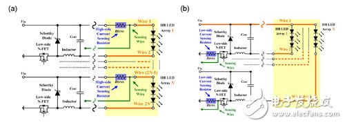
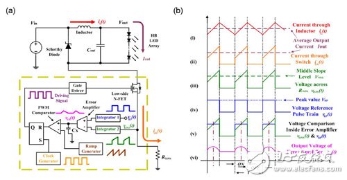
Compared with incandescent light bulbs, high-brightness light-emitting diodes (HB LED) can provide better performance and better stability, especially in the shadow of the energy crisis in the world today, the importance of high-brightness LEDs is also increasing . High-brightness LEDs are different from incandescent bulbs because both brightness and color temperature are related to the forward current of the LED. Therefore, high-brightness LEDs require accurate and stable current drive to maintain a stable light output. This basic requirement is still a big challenge for the design engineer. In addition, the drive current range of high-brightness LEDs is very wide, from 0.35 amps to the highest 10 amps or more, so the overall power efficiency must be improved, otherwise high-brightness LEDs are difficult to be widely used. This article will gradually analyze the design steps of this type of power converter, and demonstrate how to use this circuit to drive 0.35 amp high-brightness LED string lights. From the point of view of the efficiency of power conversion, a Switching Power Supply (SMPS) definitely has a greater advantage than a linear regulator. Among the many topological methods applicable to SMPS, we will select the most appropriate topology based on the available input power supply and the number of high-brightness LEDs that need to be driven. This article will discuss the breadth and simplicity of buck converters for non-isolated buck switching power supplies. First, for this application, a most cost-effective topology solution with a built-in buck converter is selected, and then the converter is adjusted to improve the system's durability and power performance. Finally, a new pulse level modulation (PLM) control method is used with the enhanced converter, hoping to use this to improve the accuracy of current regulation at the expense of the highland. The last step is to carry out the actual test of the circuit to verify its effectiveness. Floating buck topology facilitates simple gate drive circuit design Figure 1 shows a variety of different non-isolated buck converter topologies for driving high-brightness LEDs, of which Figure 1 (a) and (b) are two typical buck topology methods, and Figure 1 (c) And (d) is a floating buck topology. Generally speaking, since the Rds | on of N-MOSFET (N-FET) is lower than that of P-MOSFET (P-FET), the buck converter system in Figure 1 (a) and (c) is generally regarded as Have better power efficiency. When design engineers use buck converters, they tend to use the buck converter system in Figure 1 (a) and (c) rather than the circuits in Figure 1 (b) and (d). Fig. 1 (a) is more complicated in driving high-order N-FETs than Fig. 1 (c) driving low-order N-FETs. The reason is that Fig. 1 (a) uses self-bootstrapping gate drive technology, except for In addition to the gate drive voltage power supply Vcc shown, the circuit also includes a rectifier diode and a flywheel capacitor. The same situation can also be applied to Figure 1 (d) and Figure 1 (b). For a simpler gate drive circuit design, the topology of the buck converter shown in Figure 1 (c) will be better than that in Figure 1 (a). This is also the case with a floating buck converter with a low-side N-FET Yin. Figure 1 The buck converter suitable for driving high-brightness LEDs, its power switching technology uses (a) high-order N-FET, (b) high-order P-FET, (c) low-order N-FET, (d) Low-order P-FET Improve LED efficiency through accuracy tradeoffs The floating buck converter in Figure 2 is used to drive a long-distance high-brightness LED array with multiple light strings. In the existing system, whether it is based on heat dissipation, unfavorable operating environment, convenient maintenance or module replacement problems Most of the controllers are separated from LEDs. Typical examples include large outdoor commercial electronic billboards and building exterior lighting. Placing the current-sense resistor RISNS under the main power switch makes it easier to use low-end current sensing, which reduces the number of lines by nearly half. More importantly, the shorter current sensing circuit can prevent the LED current regulation from electromagnetic interference. In the system of Fig. 2 (b), due to the redesigned position of RISNS, its power efficiency is improved a lot compared to Fig. 2 (a). In addition, based on the low-order N-FET and RISNS in Figure 2 (b), only the inductor current will be conducted on the upper slope of the cycle, while RISNS in Figure 2 (a) can cover the entire period of the inductor current. 2 (b) The power loss of RISNS is the power loss of RISNS in Figure 2 (a) times the switching duty cycle, and the value of this duty cycle is usually lower than 1. Therefore, the power loss of RISNS in Figure 2 (b) will reduce a switching cycle factor, and the saved power P can be expressed by the following equation: Figure 2 The buck converter used to drive multiple long-distance high-brightness LED light strings, the technologies used are (a) high-end current sensing resistor (the number of remote lines is 2N), (b) high-end current sensing Measuring resistor (the number of long-distance lines is N + 1) In the equation, RISNS is the current sensing resistor, D is the duty cycle, Ipeak is the peak value of the inductor current, L is the inductance value, T is the switching cycle time, and Vout is the output voltage. Figure 2 (b) uses the traditional control method to adjust the peak current. Although a larger inductance value can make the adjusted peak current closer to the actual average current of the system, this approach lacks complete considerations, and also It is easily affected by changes in line voltage and component values. PLM solves the average current adjustment of LED string In conjunction with the reconfiguration of the sensing resistor RISNS, the floating buck converter is arguably the simplest architecture for driving high-brightness LEDs, and is also the most durable and power-efficient system solution. However, the traditional control method can only adjust the peak current, but cannot provide the actual average current adjustment for the LED string. In order to solve this problem, a brand new control method-pulse level modulation control came into being. Figure 3 (a) shows the schematic diagram of the PLM architecture applied to the floating buck converter, while 3 (b) shows the main waveforms of the PLM circuit. The traditional SMPS control method integrates an error amplifier, which can minimize the adjustment error relative to a fixed reference voltage. As for the PLM, it applies the error amplifier to the time integration VISNS (t) of the sense waveform, and the adjustment is performed relative to the time integration VRP (t) of the reference waveform. The waveform (v) in Figure 3 (a) indicates that the PLM is adjusting the trapezoidal pulse train of the sensing signal. The adjustment is performed relative to a square wave pulse train with a reference level. Since both have the same duty cycle, the midpoint of the trapezoidal slope is the same as the reference level. Based on the linear characteristic of the above intermediate point, the average inductor current or the average LED current will be adjusted to be equal to the reference current. Figure 4 shows the adjustment process in the closed loop operation of Figure 3 (a). Figure 3 (a) is a schematic diagram of the PLM floating buck converter; (b) is the main waveform of PLM Figure 4 VISNS and VRP waveforms under closed loop operation
The PZDK series of smart chargers use high frequency switching rectification power modules. The charger is a smart charging device that was developed based on the technical requirements of the AGV (Automated Guided Vehicle) battery pack (group) charging. The working process of the charger is controlled by the microprocessor in real time, automatically turned on/off, and the operation is simple, safe and reliable. It uses a microprocessor as the main control unit and a color touch screen as a human-machine interface with flexible human-machine dialogue. The user can view the operating parameters and working status through the touch screen.
Lifepo4 Battery Charger,Scr Battery Charger,Lifepo4 Battery Packs Chargers,Thyristor Controlled Rectifier Charger Xinxiang Taihang Jiaxin Electric Tech Co., Ltd , https://www.chargers.be
![]()