Design of three-axis magnetoresistive sensor module based on HMC1022 and HMC1021
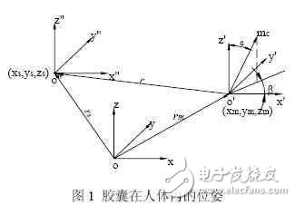
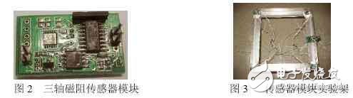
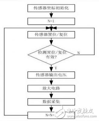
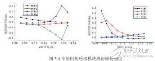
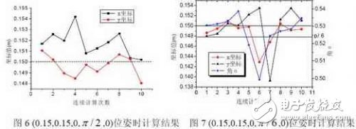
1. Introduction With the rapid advancement of MEMS (Micro-Electro-Mechanical Systems) technology, endoscopic systems have seen significant progress, especially in the field of wireless capsule endoscopes for the human gastrointestinal tract. This innovation represents a major breakthrough in medical electronic endoscope systems. As research into capsule endoscopes continues to grow, several challenges remain. The 2004 European Technical Report highlighted that achieving motion and posture control is one of the primary issues, including motion control and positioning problems. Ensuring accurate real-time location detection of these miniature medical capsules within the body is crucial for effective diagnosis and treatment. Traditional positioning methods for micro-diagnostic devices inside the body typically rely on ultrasonic imaging, nuclear medicine imaging, or fluorescence modeling. However, these techniques are often costly, complex, and may involve radiation exposure, making them unsuitable for long-term dynamic positioning. To address these limitations, researchers have explored simplified magnetic positioning models and dynamic tracking technologies to improve accuracy and efficiency. To meet the demands of precise in vivo positioning of microcapsules, the author designed a three-axis magnetoresistive sensor module based on HMC1022 and HMC1021. After signal amplification through a two-stage circuit, a data acquisition system was developed for multi-point measurement of the capsule's magnetic field strength. This system features higher sensitivity compared to previous designs and is arranged optimally to ensure large measurement ranges and enhanced detection accuracy. 2. Capsule Positioning Detection Principle Magnetic induction positioning works by utilizing the Hall effect of magnetoresistive sensors. A permanent magnet generates a specific spatial magnetic field distribution depending on its orientation and distance. By detecting changes in magnetic field parameters, it is possible to determine the spatial position of the magnet and thus locate the capsule within the body. In the human body, the capsule can be treated as a rigid body. Inside the capsule, cylindrical permanent magnets are placed to facilitate magnetic field sensing. As shown in Figure 1, the capsule's position and orientation in space can be described using the position of a point inside the capsule and the angles formed between the magnetic moment direction of the permanent magnet and the cylindrical coordinate system. The center coordinates of the capsule, along with the angle between the magnetic moment direction and the cylindrical coordinate axis, define its spatial position. When the size of the cylindrical permanent magnet is much smaller than the distance from the magnetic sensor, it can be approximated as a magnetic dipole. The magnetic induction at the sensor can then be expressed mathematically as follows: Here, the magnetic moment vector of the capsule corresponds to its spatial position and coordinates. The position vector of the magnetoresistive sensor module relative to the capsule is used to calculate the magnetic field components. If five unknowns need to be solved, at least two three-axis magnetoresistive sensor modules must be used to achieve accurate positioning. 3. System Hardware Design The hardware of this system includes four sets of three-axis magnetoresistive sensor modules (each with built-in set/reset circuits), an amplifier circuit, and a data acquisition card. 3.1 Magnetoresistive Sensor Module Figure 2 shows the designed three-axis magnetoresistive sensor module composed of HMC1022 and HMC1021, which are mounted perpendicularly. The built-in set/reset circuit helps measure the magnetic field intensity of the internal magnet. HMC1022 measures magnetic induction in two directions, while HMC1021 measures it in one direction. These sensors are designed to reduce temperature drift, nonlinear errors, and signal loss caused by high magnetic fields. 3.2 Amplifying Circuit As the distance increases, the magnetic field strength of the permanent magnet decreases rapidly. To compensate for this, an AD620 amplifier was used in the experiment, providing a gain of 1000 times to ensure that the resolution of the data acquisition card exceeded that of the sensor output. 3.3 Data Acquisition A PCI-1716 data acquisition card was used to collect signals from the amplifier circuit and send them to a computer for processing. LabVIEW software was employed to perform analog signal acquisition and A/D conversion. 4. Experimental Procedure Figure 4 illustrates the block diagram of the experimental process. Figure 4: Experimental Step Flowchart The experiment followed these steps: (1) During the sensor coordinate initialization, the positions of the four three-axis magnetoresistive sensor modules were fixed and recorded. These values were then used in equation (1) for later calculations. (2) After each movement and stabilization of the capsule, the distance between the capsule and each sensor module was recorded. The set/reset circuit improved the sensor's sensitivity. (3) After the set/reset, the magnetoresistive sensor module produced a measurable voltage, which was amplified and collected for further analysis. The results were compared with the calculated values from step (1). 5. Experiment and Result Analysis In the experiment, four magnetoresistive sensor modules were placed at the four corners of a cube-shaped frame (0.3m x 0.3m x 0.2m). Their initial coordinates were recorded. During the test, the capsule’s magnetic moment direction was adjusted, and it moved along a straight line every 3 cm. After secondary positioning, the data was collected sequentially. As shown in Figure 5, the magnetic field strength measured by sensor A decreased continuously, while B and C showed increasing trends, and D increased slowly. When comparing the experimental data with the calculated results, the error remained within ±10%. The designed magnetoresistive sensor module accurately captured the capsule’s magnetic field during movement. Additionally, for three different capsule positions, the calculation was repeated 10 times. One selected pose point was (0.15, 0.15, 0, , 0). As shown in Figure 6, the x and y coordinates fluctuated around 0.15 with an error of ±3%, while the z-coordinate and angular values showed excellent accuracy. For another pose point (0.15, 0.15, 0, , 0), where the magnetic moment direction and axis angle were 30°, the coordinate error expanded to 7%, and the axial error reached 5%. Other parameters remained consistent and accurate. The experiments and results confirm that the designed system can accurately measure the capsule’s magnetic field during movement, enabling precise spatial positioning and orientation. It should be noted that when the capsule is located in the central area of the sensor modules, the accuracy of the calculations is highest. 6. Conclusion This paper introduces a new experimental system to study capsule endoscope positioning using high-sensitivity magnetoresistive sensors. Both theoretical principles and experimental results demonstrate that the spatial magnetic field distribution of a permanent magnet can be used to locate the capsule. The analysis of the experimental results confirms that the system achieves high accuracy in determining the capsule’s position and orientation during movement. This technology has great potential for application in medical diagnostics, significantly improving the accuracy of clinical disease detection. Fiber Optic Splice Closure,Fiber Optic Splice Case,Fiber Splice Closures,Outdoor Fiber Optic Splice Closure Cixi Dani Plastic Products Co.,Ltd , https://www.danifiberoptic.com