Design of CAN network communication for process analysis instrument
introduction In the process control of modern process industries, analysis and detection have the characteristics of online, multi-component, and real-time detection, and there are strict requirements for analytical instruments in terms of stability, reliability, speed, and accuracy. The widely used industrial chromatograph adopts the principle of chromatographic separation, and the analysis period is as long as several minutes to tens of minutes, making it difficult to achieve direct quality control of the process. New technologies such as process Raman spectrometers and laser modulation spectrometers are currently expensive, and the key technologies are still in the research stage, which is difficult to popularize. The use of mature technology single-detector single-component process analysis instruments, through the analysis of sensor combination technology and embedded computer technology, to achieve multi-component real-time detection and establish a simple and fast analytical instrument communication network system has become a domestic and foreign analytical instrument research and development One of the hot spots. The multi-component gas analyzer based on single chip microcomputer (80C196) or microprocessor (DSP, ARM, etc.) adopts powerful CPU, which can quickly measure various thermal parameters of various combustion equipment in real time. According to the measurement data, the air volume is adjusted by the automatic adjustment device to maintain an appropriate air / fuel ratio, so that the fuel system reaches the optimal operating state to obtain the highest combustion efficiency and the lowest fuel consumption. The instrument can also measure CO, SO2, NO, NO2, smoke blackness and other parameters, and is equipped with LCD screen, keyboard and other peripherals. CAN (Controll Area Network) is one of the most widely used field buses in the world. It uses a serial multi-controller communication protocol that can effectively support distributed real-time control, and has high security and up to 1Mbps Communication rate. A CAN bus network structure diagram including a PC and n-1 (n≤110) intelligent nodes is shown in Figure 1. The transmission of information adopts CAN communication protocol, and the transmission medium uses twisted pair. If it is necessary to further improve the anti-interference ability of the system, optical isolation can be added between the controller and the transmission medium. The power supply adopts DC-DC converter and other measures. 1 Development of CAN network application layer protocol for analytical instruments The international standards of CAN only define the specifications of the physical layer and the data link layer. Since the number of CAN bus network nodes constructed by this project is not large, all nodes are designed by the project team and do not need to interface with international standard equipment, so Here, according to the specific situation of this project, a simple CAN application layer protocol is formulated. According to the requirements of the factory, the initial network planning should accommodate at least 16 nodes. The host computer collects the information of each analysis instrument, including the analysis content of gas components, error information and some parameters of the measured gas, such as temperature, pressure, flow rate, etc., and also returns some control information to the intelligent node. In each analysis cycle, the gas component analysis result of the slave node is sent to the master node. After receiving the content of all the components to be measured, the master node sends all the information to the host computer. Any analysis instrument in the network can be used as a master node or slave node, even in the absence of a host computer can also be used as a host computer. In the CAN system, the 11-bit (standard frame) or 29-bit (extended frame) identifier is used to identify the meaning of the data. The identifier determines the priority and waiting time of the information, and also affects the applicability of information filtering. Therefore, a reasonable and efficient information identifier ID allocation scheme is a prerequisite for giving full play to the performance of the CAN bus. There are 32 mailboxes on the F2812 DSP chip, one of the main controllers of the analysis instrument. In SCC mode, 0-15 mailboxes are available. In eCAN mode, all 32 mailboxes are available. It is convenient for the master node to receive and receive information from the slave nodes. storage. Therefore, it is recommended to use the analytical instrument whose main controller is F2812 as the main node in the network, select the eCAN mode, use the standard identifier (11 bits), and perform the static allocation strategy shown in Table 1 to meet the host computer. And the master node to identify the source and meaning of the frame. 2 Network communication program 2.1 Initialization of upper computer The upper computer side mainly completes the collection and display of the analysis results of each analysis platform, using a PC and a CAN communication card KPCI-8110. The independent CAN controller SJA1000 is integrated on the KPCI-8110. SJA1000 is used for moving target and area network control (CAN) in general industrial environment. It must be initialized before use. The host computer display interface is written in VB, a visual object-oriented high-level language suitable for rapid development. The KPCI-8110CAN adapter card provides .dll drivers and .lib library functions. The configuration and data reading and writing of the CAN adapter card can be realized by calling related driver functions in the VB program. The process of receiving data from the host computer is shown in Figure 2. After the data is received by the host computer, it is stored in a large-capacity memory buffer pool. The user only needs to query the amount of data in the buffer pool in real time through the function CAN_ReadDataNum (mindex), and then read and save it in time through the function CAN_ReadBlockData (mindex, num, obyte) . Where obyte is the start pointer of the received data. CAN_ClearBlock (mindex, num, obyte) is to clear the buffer pool space starting from obyte pointer. Note: Since the SJA1000 CAN controller stores 8 bits of data per address, and the F2812 built-in CAN controller stores 16 bits of data per address, and the identifier of the standard data frame does not start from the beginning of the byte, so define The identifier should be defined according to the requirements of different controllers. For example, the F2812 built-in CAN controller defines the data frame identifier as 344 0000 (bit28-bit18 is the identifier bit), and the corresponding identifier of the SJA1000 independent controller should be 1A20 (bit15-bit5 are the identifier bits).
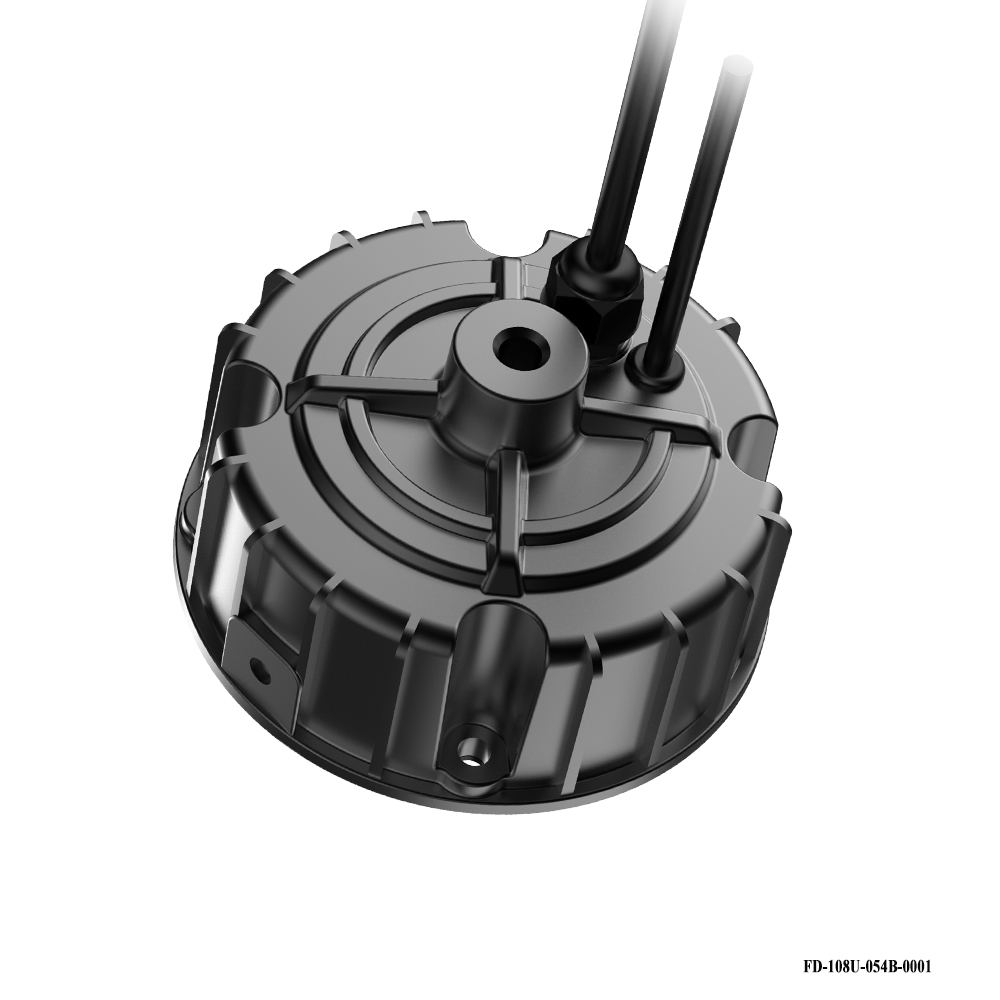
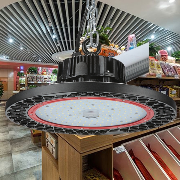
Round High Power High Bay Fixtures Driver
High power 100W or more, the specific anti-high pressure waterproof performance, AC100-277V input, high PF value,can do the triac-dimming or 0-10V/PWM/RX dimming,short circuit protection,class 2 satety output design, passed the UL/FCC/TUV/RCM/CB/CE Certified. Europe and North America market.
Constant Current LED driver, UL Dimmable Transformer, With global manufacturing standards and various certifications including CE, UL and FCC, our lighting products are sold in domestic market and are exported to various international markets including US, UK, France, Germany, Australia, Africa, Korea etc. We offer a wide range of Led Lighting Solutions which includes LED Linear Lighting or System, , LED Lams, LED High bay lights etc. Maximize beauty of your workplace with our beautiful Warehouse Lighting, Warehouse Lights Driver, Workshop Lighting, Supermarket Lighting and Factory lighting solutions.
Application: Specifically for high bay light, High Power Led Driver above 100W,normal for outdoor for waterproof, AC100-277V, 0-10V/PWM/RX dimming,short circuit protection,class 2 satety output design, passed the UL/FCC/TUV/RCM/CB/CE Certified. Europe and North America market.
Parameter:
Input voltage: 100-277vac
Power:240W
IP degree: IP65
FAQ:
Round High Power High Bay Fixtures Driver Led Grow Light Led High Bay Light,Switching Power Supply,240W Ufo High Bay Driver,Ufo Led Driver ShenZhen Fahold Electronic Limited , https://www.fahold.com
Figure 1 CAN network structure diagram of n nodes 
Figure 2 Flow chart of the host computer interface functions
output voltage: 25-143vdc
current: 100mA-8000mA.
Power factor: >0.9
Dimming:0-10V / PWM / RX / DALI.
>=50000hours, 5 years warranty.
certificate: UL CE FCC TUV SAA ect.


Question 1:Are you a factory or a trading company?
Answer: We are a factory.
Question 2: Payment term?
Answer: 30% TT deposit + 70% TT before shipment,50% TT deposit + 50% LC balance, Flexible payment
can be negotiated.
Question 3: What's the main business of Fahold?
Answer: Fahold focused on LED controllers and dimmers from 2010. We have 28 engineers who dedicated themselves to researching and developing LED controlling and dimming system.
Question 4: What Fahold will do if we have problems after receiving your products?
Answer: Our products have been strictly inspected before shipping. Once you receive the products you are not satisfied, please feel free to contact us in time, we will do our best to solve any of your problems with our good after-sale service.