Measurement of passive intermodulation distortion in communication system
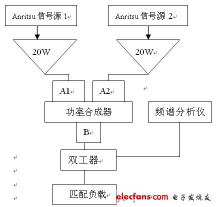
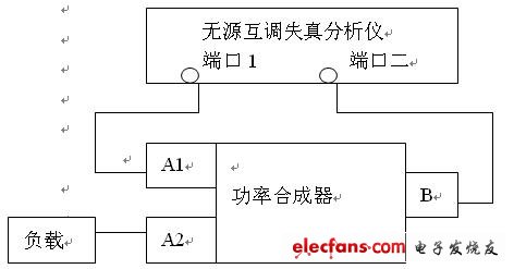
Foreword In modern communication systems, when carrier signals of multiple frequencies pass through some passive devices, intermodulation distortion will occur. Passive components such as antennas, cables, filters, etc., because of their unreliable mechanical connection, use materials with hysteresis characteristics, contaminated contact surfaces, etc., signals of different frequencies are mixed non-linearly at the points where the materials are not Intermodulation products of different amplitudes are generated, and these intermodulation distortion signals appear as interference signals in the communication band, which reduces the signal-to-noise ratio of the system and seriously affects the capacity and quality of the communication system. In fact, in our usual design and measurement, we generally pay more attention to active intermodulation, such as the intermodulation distortion generated by amplifiers, mixers, etc., and the measurement of active intermodulation due to intermodulation distortion The relative amplitude difference with the carrier is small, so the measurement is easy to implement. With the development of communication systems and the improvement of system quality, the measurement and analysis of passive intermodulation will be paid more and more attention. The establishment of measurement When measuring the intermodulation distortion of the power combiner, the traditional measurement method as shown below can be used: Figure 1 As shown in the figure, the high-power continuous wave signal output from Anritsu's 68347 signal source is input to the two ports of the power combiner. The frequency of each carrier is appropriately set within the bandwidth required for measurement. The power combiner has two functions: it is the device under test, and it combines two signals into one signal. The intermodulation signal generated by the power synthesizer is transmitted to the duplexer port, and the intermodulation signal within the receiving bandwidth is measured with a spectrum analyzer. Modern passive intermodulation analyzer can output pre-assembled dual frequency signals. The intermodulator has two radio frequency ports. Port one can output two high-power dual-frequency signals. After passing the device under test, it enters port two of the analyzer. The reflected signal of port one also enters the receiver of the analyzer. The analyzer can work in two states, transmission mode and reflection mode, measuring transmission intermodulation distortion and reflection intermodulation distortion of the device under test respectively. In fact, for the device under test, the intermodulation distortion produced by different factors is a vector signal, and their relative phase relationship will determine the total amplitude of the intermodulation distortion of the device under test in a specific state. In transmission measurement, different intermodulation products are in phase when they arrive at port two. In reflection measurement, the intermodulation distortion arriving at port one is the total response of port one and the phase shift response of the intermodulation source on port two. Therefore, the reflection intermodulation distortion is a function of frequency and electrical length of the device under test. Use an intermodulator to measure the intermodulation response of the above power synthesizer. The measurement connections are as follows: Figure II As shown in the figure, the port of the intermodulator is connected to the measured input port of the power combiner, so that the intermodulation distortion of the A1, A2 and B ports of the power combiner can be measured. The transmission mode of the intermodulator measures the forward intermodulation distortion of port B, and the reflection mode measures the intermodulation distortion of port A1. As shown in the figure, if port A1 is used as the drive port, port A2 should be connected to a low intermodulation distortion load to ideally test the intermodulation distortion of the power synthesizer. By switching ports A1 and A2, the intermodulation of each input port of the power combiner can be measured. Compare the above two methods: In Figure 1, the power combiner connection and port B carry two continuous wave powers. The measured intermodulation distortion is the total intermodulation distortion of these two factors. If the incident signal at each port is a non-modulated signal, this method accurately measures the true intermodulation performance of the power combiner, but is limited by the inherent intermodulation distortion of the spectrum analyzer. If both the output and input ports of the power combiner are modulated signals, the measurement results provided in Figure 2 are more meaningful. Fliying Platform , Industry Drone Flight Platform,Long time Flight Drone, Heavy Duty Drone ,Heavy Payload Drone Fliying Platform, Industry Drone Flight Platform,Long time Flight Drone,Heavy Duty Drone,Heavy Payload Drone shenzhen GC Electronics Co.,Ltd. , https://www.jmrdrone.com