MC9S12XHZ512 realizes automobile instrument cluster
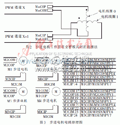
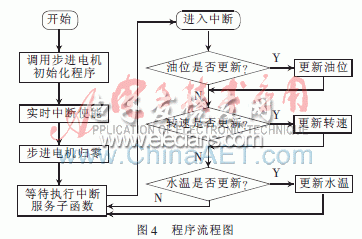
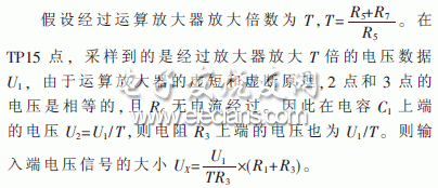
Car instrumentation is an important device used to display and record various driving information of the car and the operation of the engine. The stepper motor can be used to control the position of the rotating shaft of the motor very accurately. It does not require expensive sensors and control circuits. The position of the input pulse is tracked, and the stepper motor has good start and stop response functions. Therefore, in order to meet the needs of automobile instruments with high anti-interference ability, high reliability, high integration, multi-function and intelligence, this paper designs a bus-type automobile with analog sampling multiplexing and with stepper motor Intelligent combination meter . 1 Composition principle of instrument structure The composition module of the instrument is shown in Figure 1, which is composed of a collection control module, a display module and a peripheral circuit module. Both the display module and the peripheral circuit module are connected to the acquisition control module. The acquisition control module includes a main processor and an input and output module, and the input and output module is connected to the main processor. The display module includes a display interface module and a display processor, and is connected to each other. The analog sampling multiplexing circuit in the acquisition control module includes a resistance network adjusting circuit and an analog multiplexing input signal pre-processing circuit. The input signal adjusted by the resistance network adjusting circuit is processed by the analog multiplexing input signal pre-processing Circuit selection and transmission to the main processor of the acquisition control module. 2 Stepper motor drive design and interrupt control 2.1 Drive design of stepper motor Speedometer, tachometer, oil level gauge and water temperature gauge are all driven by stepper motor. When designing the hardware, it is only necessary to connect the single-chip microcomputer and the stepping motor with leads. Figure 2 shows the connection method when a single stepper motor works in dual full-bridge mode. It is controlled by two pulse width modulation (PWM) channels, channel X controls coil 0, and channel X + 1 controls coil 1. The schematic diagram of the actual circuit is shown in Figure 3. M1, M2, M3, and M4 are the speedometer, tachometer, oil level gauge, and water temperature gauge, respectively. 2.2 Use real-time interrupt RTI to control stepper motor In order to solve the real-time problem, the real-time interrupt RTI is used to control the stepper motor. RTI is a sub-module in the clock and reset generator that can generate real-time interrupts. The frequency division coefficient adopted in this article is 3 & TImes; 215, that is F = 8 M / 3 × 215 = 81.38 Hz, and the interval time of each interruption is t = 1 / 81.38 = 12.3 ms. The microcontroller changes the output of all stepper motors every 12.3 ms, which in turn changes the pointer position of the stepper motors. When the control mode of the stepper motor is double four beats, each time the interruption is given to the instruction (permanent magnet) to turn it 90 ° (a substep), that is, the rotor rotates once in real time every 4 times (a full step ). Additional programs can be run during the RTI real-time interruption interval. Because the data of the oil level meter, engine tachometer and water temperature meter are all transmitted from the CAN bus, the procedures of these three tables are organized into the same module. The functions of the tachometer and water temperature meter are the same as the oil level meter. . The program flow chart is shown in Figure 4. When using a real-time interrupt to control a stepper motor, the stepper motor can only take one minute at a time. Because the output of the four-step step within a week is different at the pin, first determine the position of the rotor. Each interruption must judge whether the variable of the stepper motor is updated, and judge whether it is forward or reverse to decide which single step function to call. 3 Analog sampling multiplexing circuit design The analog acquisition multiplexing circuit designed by this instrument can realize the measurement of voltage, current and resistance signal by adjusting the resistance network, as shown in Figure 5. (1) When the connected analog quantity is a voltage signal, the circuit adjustment is shown in Figure 6. (2) When the connected analog is a current signal, the circuit adjustment is shown in Figure 7. In the actual application process of this circuit, the size of the relevant resistance in the resistance network can be calculated and determined according to the type of signal to be sampled, the signal range and the value of the reference voltage of the chip analog interface. This design develops the driver program of the stepper motor and adopts real-time interrupt control of the stepper motor, which satisfies the needs of automobile instruments with high anti-interference ability, high reliability, high integration, multi-function and intelligence.
FTTH Fiber Optic Socket Terminal Box, fiber termination box provides a mini density wall-mounted solution for next generation networks, which aims to provide and manage minimum numbers of fibers in a limited space.
It is normally installed in the way of wall-mounted. Widely used in FTTH access network, telecommunication networks, CATV networks, data communications network, local area networks, indoor and outdoor application.
Mini FTTH terminal box is designed specially for FTTx application, which suits for jointing fibers pigtail and it protects fiber optic splices and helps to share out the connectivity to individual customers. Optical Termination Box is designed to connect raiser/distribution cables to subscriber`s drop cable in FTTx networks. It has 1 input port and 1 output ports on the bottom and it is easy to install on the wall.
FTTH Fiber Optic Socket Terminal Box Optical Fiber Terminal Box,Fiber Access Termination Box,Fiber Optic Terminal Box,Fiber Optic Junction Box,Fiber Optic Cable Junction Box Sijee Optical Communication Technology Co.,Ltd , https://www.sijee-optical.com