PT1301 mobile phone emergency charging solution
Mobile phone emergency charger:
The PT1301 mobile phone emergency charging solution is a low-start voltage (down to 0.8V), high-efficiency boost DC-DC converter. The mobile phone emergency charger implemented with PT1301 has the following advantages:
1. Low starting voltage: This feature is well reflected in the input of a single dry battery. In practical applications, users often need to make phone calls during the charging process. When the charger is unplugged and then plugged in, it is found that the charging cannot be continued. This is because some mobile phones have the function of detecting the initial charging current. When the initial charging current is less than the set value, the charging function cannot be completed. The single-segment solution implemented with PT1301 can still carry 180mA after the input voltage is 1.2V, which solves this problem well.
2. Larger charging current: single energy-saving charging current 300mA, double section 500mA.
3. Extremely high battery utilization rate: During the charging process, the PT1301 mobile phone emergency charging solution will detect the input voltage. When the input voltage decreases, the output current will decrease at the same time. In this way, during continuous charging, even if the battery voltage is as low as 0.7V (single cell) and 1.5V (dual cell), the charge can be maintained.
4. Output power protection: PT1301 mobile phone emergency charging solution has the function of dynamic load adjustment rate. Adjust the output power according to the size of the output current. When the output current is too large, reduce the output voltage to maintain a constant output power.
5. High efficiency: PT1301 mobile phone emergency charging solution has high efficiency. The single-segment scheme has an efficiency greater than 75% when inputting 1.5V; even when the input voltage is 1V, it has an efficiency of more than 70%. The efficiency of the two-section scheme is even as high as 87%.
Single section emergency charging plan
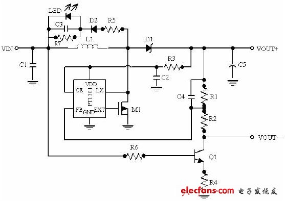
Circuit diagram
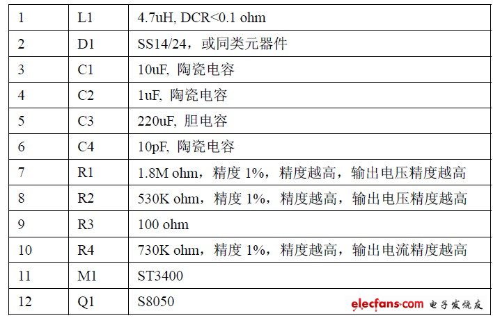
Component list:

Dual-cell charging solution

Circuit diagram
Component list
Test circuit and test notes
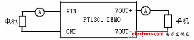
1. Because the parasitic resistance of the output terminal will affect the size of the charging current, when testing, the ammeter used at the input and output terminals should be 20A, and the thick wire (<10cm) is used to reduce the parasitic resistance.
2. The ammeter at the output should be connected in front of the mobile phone.
3. In the single-section scheme, the user can increase the charging current by reducing the resistance R6, but it is recommended not to exceed 500mA, otherwise it will burn Q1.
Similarly, for the two-segment solution, users can increase the charging current by reducing R4, but mobile phones usually have a limit on the maximum charging current.
When the mobile phone is protected due to excessive charging current, the mobile phone will still maintain a small current for charging, but the efficiency at this time will be extremely low. Therefore, it is recommended that the charging current should not be greater than 500mA.
Smd Buzzer,Smd Piezo Buzzer,Smd Micro Buzzer,Smd Magnetic Buzzer
NINGBO SANCO ELECTRONICS CO., LTD. , https://www.sancobuzzer.com