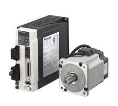
**Introduction to Servo Drive**
Servo drives, also known as servo controllers or servo amplifiers, are essential components used to regulate the operation of servo motors. They function similarly to frequency converters used with standard AC motors and are integral parts of a complete servo system. These devices are primarily employed in high-precision positioning systems, where they enable accurate control through three main modes: position, speed, and torque. This makes them a key technology in advanced motion control applications.
In modern automation systems, such as industrial robots and CNC machining centers, servo drives play a crucial role. Particularly, those designed for controlling AC permanent magnet synchronous motors have become a focal point of research both domestically and internationally. Most current AC servo drive designs utilize three closed-loop control algorithms based on vector control—current, speed, and position. Among these, the design of the speed closed-loop is especially important, as it significantly impacts the overall performance of the servo control system, particularly in terms of speed regulation.
In the speed closed-loop of a servo drive, precise real-time measurement of the motor rotor’s speed is critical to enhancing both dynamic and static characteristics of the loop. To balance accuracy with cost, an incremental photoelectric encoder is typically used as the speed sensor, and the M/T method is commonly applied for speed measurement. While this technique offers good accuracy and a wide range, it has several inherent limitations:
1) It requires at least one full code wheel pulse during the measurement period, which restricts the minimum measurable speed.
2) The two timers used for speed measurement often struggle to maintain strict synchronization, leading to reduced accuracy in environments with significant speed fluctuations. As a result, traditional speed loop designs face challenges in improving the speed tracking and control performance of servo drives.
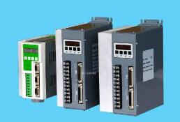
**Servo Drive Principle**
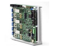
A servo driver typically uses a digital signal processor (DSP) as its core control unit, allowing it to implement complex control algorithms and enabling digitalization, networking, and intelligence. The power stage usually incorporates an intelligent power module (IPM), which integrates the drive circuit along with protection features like overvoltage, overcurrent, overheating, and undervoltage detection. Additionally, a soft start circuit is included in the main circuit to minimize the impact of startup on the drive.
The power driving unit first rectifies the input three-phase AC or commercial power using a three-phase full-bridge rectifier, converting it into DC power. This DC power is then converted back to AC via a three-phase sinusoidal PWM inverter to drive the AC servo motor. In essence, the entire process involves AC-DC-AC conversion. The rectifier unit generally uses a three-phase full-bridge uncontrolled rectifier circuit.
Servo drives typically support three control modes: position control, torque control, and speed control. In position control mode, the motor's rotation speed is determined by the frequency of external pulse inputs, while the rotation angle is determined by the number of pulses. Some servos allow direct assignment of speed and displacement via communication. Position control offers very tight control over both speed and position, making it ideal for precision positioning applications.
In torque control mode, the motor’s output torque is set externally through analog input or direct address assignment. This torque can be adjusted in real-time via analog settings or through communication. It is widely used in winding and unwinding systems where material tension must be carefully controlled, adjusting torque based on the radius of the winding to maintain consistent stress on the material.
In speed control mode, the motor’s speed is regulated using analog input or pulse frequency. When combined with the upper-level PID control, it can also achieve positioning, provided that feedback from the motor or load position is available. Some systems use direct load position feedback, allowing the motor encoder to only measure speed, while the final load position is detected separately. This reduces intermediate transmission errors and improves overall positioning accuracy.
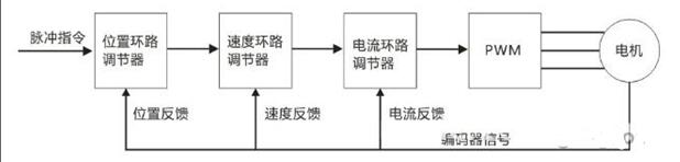
*Servo drive working principle diagram*
**Servo Drive Application**
Servo drives are extensively used in various industries, including injection molding machines, textile machinery, packaging equipment, and CNC machine tools. Their ability to provide precise control and high performance makes them indispensable in modern automated systems.
**Servo Drive Selection**
Choosing the right servo drive requires careful consideration of multiple factors. Here are some key points to keep in mind:
1. **System Requirements**: Before selecting a model, analyze the system requirements, such as size, power supply type, power rating, and control mode. Understanding these will help you choose the most suitable drive.
2. **Motor Compatibility**: Ensure the driver supports the type of motor being used, such as DC brush, sine wave, or trapezoidal wave motors. The driver’s continuous output current should exceed the motor’s rated current, and its capability to handle the motor’s back EMF and maximum speed should be considered.
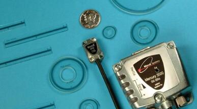
3. **Feedback Components**: Feedback sensors are crucial for closed-loop control. Common options include encoders, tachogenerators, and other position or speed sensing devices. When selecting a driver, ensure it supports the required feedback type and signal format.
4. **Control Modes**: Servo drives offer three main control modes—torque, speed, and position. Each mode has different command formats. Torque and speed can be controlled via analog signals, while position control often uses pulse + direction. Some systems also use bus-based communication like EtherCAT.
5. **Accuracy Needs**: System accuracy depends on several factors, and the servo drive plays a major role. Digital servo drives and linear amplifiers are common choices. Linear amplifiers are known for low noise, high bandwidth, and distortion-free current zero crossing.
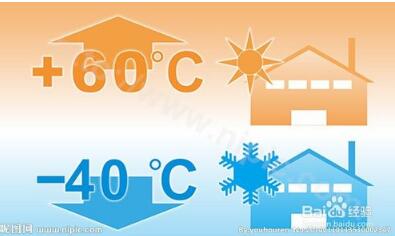
6. **Power Supply and Environment**: Consider the power supply type—DC or AC—and any specific power requirements. Environmental conditions, such as temperature and operating environment, should also be taken into account, including whether a protective cover is needed.
3D Uv Printer Machine
.Using high-quality UV ink, the color is realistic, restore the color of the picture
.Using Epson 10th generation nozzles, multi-channel printing C, M, Y, K+ white color to achieve white color one-time molding, and can achieve complex effects such as any part, no wire drawing, no stripes, optical resolution up to 5760*1440dpi, and the printing effect is clearer
.Smart Micro Touch Computer,Equipped with 8-inch touch computer, touch sensitive and stable, easy to use
.The color reproduction is more realistic, with partial concave and convex hollow relief effect
Smart Uv Printer,3D Photo Printer,3D Emboss Back Skin Printer,3D Relief Back Film Printer
Shenzhen TUOLI Electronic Technology Co., Ltd. , https://www.tlhydrogelprotector.com