Measuring the DC offset of an AC signal with a chronometer
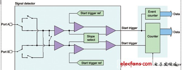
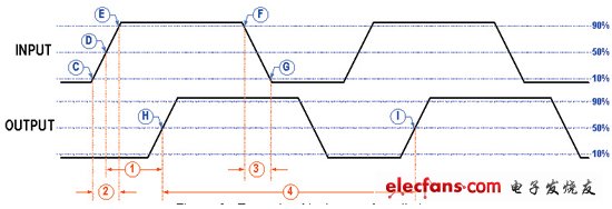
What is a chronograph? The chronograph is a semiconductor automatic test equipment (Ate) that measures the time between two events or counts the number of events. Due to the increasing complexity of testing in the semiconductor industry, and IC designers want to ensure that their ICs meet the design requirements in terms of speed and response, most chronographs come with a TMU internally. TMU is required regardless of whether the test equipment is used to test analog ICs, digital ICs, or mixed-signal ICs. Typically, TMUs are used to measure AC parameters such as frequency/cycle, propagation delay, setup and hold times, rise/fall edges, duty cycle, and signal slope. The TMU consists mainly of two parts (see Figure 1): Signal detector This section is used to detect the occurrence of an event after the input signal has appeared. By setting the parameter threshold of interest (usually the voltage parameter) and the slope of the signal change (positive or negative), the detector can trigger the counter module to start counting or stop counting when the input signal reaches a pre-set threshold. The trigger signal to start counting and stop counting can be generated by one detector, but today most TMU manufacturers integrate at least two detectors because both detectors can detect signal voltage changes below 1 mV without delay. Send the trigger signal to the counter module. 2. Counter In the TMU, the core of counting the number of occurrences or intervals of events is the start and stop triggers. For this part, resolution and accuracy are the most important factors in order to get more accurate results. Today, TMU manufacturers can easily create high-speed TMUs with resolutions up to pico-second or femto-second levels, while the counter's maximum computable time remains at a few seconds. TMU application example: In Example 1, a sine wave of amplitude 1V is fed into the TMU input port. Detector settings: Threshold voltage of interest = 0.5V Signal change slope sign of interest = positive (posiTIve, from low to high) Figure 1: TMU module block diagram As can be seen from Figure 2, point A will be detected twice, and point B will be ignored because the slope of the signal change at point B is negative (from high to low). Figure 2: Sending a sine wave to the TMU The time difference between the first and second detection of point A is the period of the input signal. The input and output pins of the digital IC in Example 2 are sent to the input port of the TMU. According to Figure 3, set the low level (VIL and VOL) ​​of the voltage input and output to 0V, and the high level ((VIH and VOH) is 5V, then Table 1 gives the corresponding TMU settings and parameters to be tested. Figure 3: Example of logic waveform timing Sensor Dustbin Automatic Dustbin Sensor Dustbin Automatic Dustbin,Automatic Sensor Recycling Dustbin,Stainless Steel Sensor Automatic Dustbin,Automatic Sensor Dustbin NINGBO ZIXING ELECTRONIC CO.,LTD. , https://www.zixingautobin.com