Dental chair control system based on μC / OS-II
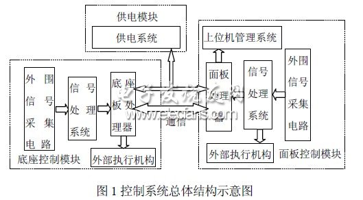
1 Introduction The dental chair controller is the core of the integrated oral diagnosis and treatment system, and its design level reflects the degree of automation of the entire system, and is also an important basis for determining the grade of the dental chair. This paper researches and develops a dental chair control system based on ARM embedded technology. The application of embedded operating system in the control system, the use of multi-task management, inter-task synchronization and communication and other functions can further improve the system reliability and real-time, and enhance the level of intelligent control and management. 2 Overall function overview The overall block diagram of the system is shown in Figure 1. The design of the dental chair control system must meet medical needs and be easy to use and operate. In addition to the four basic directions of up and down lying in the actual work, the high-end dental chair must also be able to complete tea cup water supply, flushing the pot, flushing lamp control, position data collection, X-ray transmission, and communication with the host computer. Ensure smooth and reliable movement and real-time data transmission. The dental chair control system CPU responds to the external keyboard input and executes the corresponding commands to drive the external hydraulic transmission mechanism to realize the dental chair movement and other external equipment work. Since there are many control points in the dental chair control system, and they are concentrated in the instrument panel and the dental chair base, this article divides the dental chair control system into three major modules: panel control module, base control module, and power supply module. 2.1 System hardware design Based on chip performance, power consumption, system requirements and other requirements, this system uses S3C44B0X chip and ATmega16 chip to form a dual CPU module for collaborative control. S3C44B0X is a 16 / 32-bit RISC processor produced by Samsung. Its bus structure adopts Samsung ARM CPU embedded microprocessor bus structure. S3C44B0X provides comprehensive, general-purpose on-chip peripherals, including 1 LCD controller, 5 PWM channel timers and 1 channel internal timer, 71 general-purpose I / O ports and 8 channel external interrupt sources, 8 channel 10 Bit ADC, SPI synchronous data communication serial ARM embedded dental chair control system interface, etc., has good scalability, as the main processor of dental chair system. ATmega16 is an enhanced AVR RISC structure of low-power 8-bit CMOS microcontroller, rich in internal resources, with 32 programmable I / O ports, 512 bytes of EEPROM, four-channel PWM output, 8 10-bit ADC conversion The channel and three internal timer / counter and SPI synchronous data communication serial ports are used as the core and control chip of the base module of the dental chair system to control the movement of the dental chair and collect the position data of the dental chair. The principle structure diagram of the dental chair control system is shown in Figure 2. The base control board CPU is connected to a 3 & TImes; 2 foot pedal. The CPU receives the keyboard input and executes the corresponding commands, and controls the on and off of the hydraulic drive control relays on the base module. And exercise at the visit location. Considering the safety of the user and the stability and reliability of the dental chair equipment, the CPU must monitor the feedback information of the limit switches and base obstacle protection switches in four directions in real time and make corresponding protective actions during the movement. In order to achieve the purpose of convenient use, the panel control module should also be able to control the above-mentioned movement of the dental chair and memorize the position of the dental chair in real time, so the system must realize real-time communication between the base plate and the panel. Combined with the characteristics and actual needs of the CPU chip, the serial peripheral interface (SPI) is used for high-speed data synchronization transmission. The panel CPU can receive input from the external expansion keyboard to execute the response commands, and reserves the expansion interface. Since the external devices belong to the strong power control part for the CPU, in order to maintain the control signal connection between the two and avoid electrical interference, that is, implement weak current and strong power isolation, the panel control module adds a photoelectric isolation circuit. The digital adjustment design of the brightness of the shadowless lamp adopts the PWM method. S3C44B0X has 5 timers that can provide PWM output. Since the rated power of the shadowless lamp used in the system is 50W and the rated voltage is 12V, it belongs to high current operation. In order to ensure the adjustment accuracy of the shadowless lamp, the field effect tube IRF540 is used in the control circuit to cooperate with the photoelectric isolation circuit. Lightsaber could be come
true, this light stick design we make the light soft and nice. One way light
saber or two ways light saber is available. The light sick could be install on
floor and wall, indoor and outdoor are available. Different color could be
provided. Just make the life more and more interested. Fiber Optic Glow Stick Light,Fiber Optic Glow Sticks,White Fiber Optic Wands,Fiber Optic Sticks ZHONGSHAN G-LIGHTS LIGHTING CO., LTD. , https://www.glightsled.com