Design and Application of HART Protocol in Intelligent Electromagnetic Flowmeter
1 Introduction HART, or Highway Addressable Remote Transducer, is the abbreviation of Addressable Remote Sensor Expressway. It was first developed by American Rosemount company and supported by more than 80 famous instrument companies. Its feature is that it does not interfere with 4-20mA analog signals. Allow two-way digital communication. The intelligent electromagnetic flowmeter that conforms to the HART protocol can not only realize the detection and display of various flows, but also can be set remotely by the upper meter, change the zero point and range of the flowmeter, and complete functions such as self-diagnosis. It is convenient to use and maintain the flowmeter, so it has strong market competitiveness. [1] This article discusses the technical problems of the specific implementation of intelligent electromagnetic flowmeters based on the HART protocol. One is to solve the design problem of the hardware circuit, and the other is to discuss the realization of the HART protocol command set programming and the realization of the host computer software. 2 Introduction to HART protocol The HART protocol follows the OSI open system interconnection reference model developed by ISO, using the first, second, and seventh layers of the OSI model, namely the physical layer, data link layer, and application layer. 2.1 Physical layer specification The HART protocol adopts the Bell202 frequency shift keying (FSK) standard of the US telephone communication system. The analog ± 0.5mA sine wave at 4-20mA, the baud rate is 1200bps. Because the average value of the superimposed sinusoidal signal is 0, and the phase continuous frequency shift keying technology requires that the phase angle at the boundary of data bits 1 and 0 at a baud rate of 1200 Hz is continuous, the digital communication signal will not affect 4 ~ 20mA analog signal. 2.2 Data link layer specification [2] [3] This part of the agreement stipulates the format of the HART frame to realize the establishment, maintenance, and data link communication functions. The HART protocol uses redundant error detection code information, through the error detection mechanism, and the automatic retransmission request protocol (ARQ) to achieve communication data Error transmission. The data transmission related to the protocol is realized in the form of frames. Frame is the encapsulation of user data by user control and addressing information. It can only be carried out after the counting of bytes in the frame has passed the error check and the reception is correct or the physical layer informs that the signal transmission is terminated (if no carrier is detected) Frame identification. The format of the HART frame is shown in Figure 1. PREAMBLE Preamble signal. DELIM delimiter: a unique or most easily recognized character. ADDR address byte: contains the source address and destination address, the highest bit is used to indicate the address of the master device related to the frame. COM command byte: indicates the function to be performed by the field instrument. Total length of BYTE CORNT data: This value represents the number of bytes from BYTE CORNT next byte to the last (not including check byte). DATA data bytes. CHK parity: longitudinal parity. The HART protocol in the data link layer is a "master / slave" protocol. In addition to the acknowledgement command that has been received in the reply message of the slave device, many messages also contain data queried by the master device. The HART protocol allows two main devices to run simultaneously in the system, one basic main device and one sub-main device. The slave devices distribute their response command messages to the two master devices according to their different addresses. 2.3 Application layer specification [4] It specifies three types of commands in the HART message package. The first type is a general command, applicable to all products that comply with the HART protocol, and provides a functional description for devices that comply with the HART protocol; the second type is a general operation command, which is applicable to comply with the HART protocol Most of the products; the third category is the device special order, which is suitable for special products that comply with the HART protocol. 3 Hardware design of intelligent electromagnetic flowmeter based on HART protocol The hardware system circuit of the intelligent electromagnetic flowmeter with HART communication protocol adopts modular design, which mainly includes four parts: sensor module, MCU module, HART communication module and human-machine interface module. The low-frequency excitation current controlled by the single-chip microcomputer is output to the excitation coil of the sensor, and at the same time, the tiny potential signal from the electromagnetic flow sensor is sent to the single-chip microcomputer through the AD analog-to-digital conversion circuit after pre-amplification. The single chip microcomputer carries on the data acquisition to these signals, analyzes and sends to the liquid crystal display screen to display the instantaneous flow and the accumulated flow. At the same time, the single-chip microcomputer compensates the obtained flow value through the calculation formula, and realizes the remote communication with the host computer through the compensated flow signal through the HART communication module. 3.1 HART communication module design The HT2012 chip is used to realize the demodulation and modulation process of the communication signal in the HART protocol. Figure 2 shows the connection between the modem and the microprocessor. Figure 2 HART interface circuit 3.2 HT2012 and external interface The HART digital signal specification is a sinusoidal AC current signal with a peak value of 1 mA and an average value of 0 mA. This signal is converted into a sinusoidal AC voltage signal by line impedance, and the HT2012 input and output signals are 0-5V square wave signals, so the HT2012 and external Filter circuit and shaping circuit are also needed between the HART signals. As shown in Figure 3, the filter composed of TLC27 is a band-pass filter, used to reduce the noise interference of the received signal. The filter is also used to eliminate spikes in the waveform, thereby smoothing the received signal. The digital square wave generating circuit composed of TLC37 converts the sine wave filtered by TLC27 into a corresponding square wave, which is convenient for HT2012 reception. HT2012 needs to provide 460.8kHz clock signal externally, and the error of the clock frequency is required to be ± 0.1%. If directly input a 460.8kHz crystal oscillator, it will not only increase the system power consumption, but the crystal oscillator is a non-standard crystal oscillator, which needs to be customized. In order to solve this problem, a 1.8432MHz crystal oscillator is used in the system to generate a clock signal, which is then divided by a frequency divider CD4013 4 times, and a frequency division signal of 1.8432MHz / 4 = 460.8kHz can be output for HT2012. AD421 its internal voltage regulator and external field effect tube DN25D adjust the voltage input to AD421, can provide + 3.3V voltage as a power supply for other devices. The FSK signal sent by HART is sent to the AD421 through a capacitive coupling, which is converted into a corresponding ± 0.5mA sinusoidal current signal to realize the conversion of the voltage signal to the current signal. At the same time, it is superimposed on the current of 4-20mA to the receiving device Realized the exchange of information of HART protocol. The coupling capacitance of this circuit is taken as 0.0033μF. Indoor Fiber Termination Box can be supplied empty or fully loaded with adapters and pigtails. Meanwhile they are often deployed in FTTH applications for connecting feeder and distribution cables. The indoor fiber terminal box provides efficient cable connections between outside plant cables and equipment inside the buildings and communications facilities . Indoor Fiber Termination Box can be wall mounted or pole mounted and provides various accessories to avoid any unexpected damage to the fiber. Indoor Fiber Termination Box Indoor Fiber Termination Box,Fiber Termination Box,Fiber Optic Termination Box,Fiber Optic Box Foclink Co., Ltd , https://www.scfiberpigtail.com
The demodulation process of the HART signal: After the pulse signal output by the band-pass filter enters the HT2012, the modem demodulates the 1200Hz and 2200Hz of the pulse signal into digital 1 and 0, and then outputs the digital signal from the ORXD port of the HT2012, CPU Judge the received data and perform the corresponding tasks. 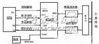
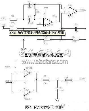
As shown in Figure 4, the role of the buffer 74HC126 is to make the rising and falling edges of the square wave tend to be gentle, so that the signal meets the requirements of the rising and falling edges of the signal waveform required by the HART physical layer specification, because the gentler Rising and falling edge time can reduce crosstalk with other networks.