Wireless transmitter circuit diagram and working principle analysis
Wireless transmitter circuit diagram and working principle analysis Q1 is a common-emitter transformer-coupled oscillation circuit: the load is the transformer coil of the transformer T. After the collector output signal is coupled by T, the secondary pole is sent to the base via C1 to form positive feedback and start vibration. The base is fed into a low-frequency modulation signal at the same time to amplitude modulate the high-frequency oscillations generated. There should be a connection point at T, L1 and 9V. Since this circuit has no DC bias, the circuit works in Class C amplification. The phase between the primary and secondary of T is opposite, that is, when the collector current of Q1 increases, the primary induced electromotive force of T is positive and negative, and the secondary generates an induced electromotive force of positive and negative, which increases the charging current of C1. The opposite is true when the collector current decreases. The frequency is determined by the capacity of C1 and the inductance of T.
LED corn lamps are changing the way we think about high-powered lighting. Led Corn Lamp is great replacement for Parking Lot Lights.Retrofit your outdated HID fixtures with energy-efficient Corn Cob Led Lights for high bays, low bays, post tops, mini post tops, and PAR 38 fixtures.Corn Cob Led for Public Lighting has a high efficiency and has minimal maintenance costs.
Led Corn Lamp Led Corn Lamp,Corn Cob Led Lights,Corn Cob Led,Corn Light Bulb Shenzhen Bbier Lighting Co., Ltd , https://www.chinabbier.com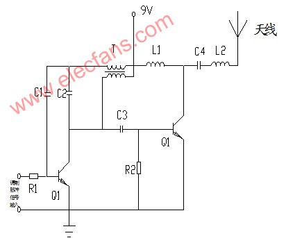
Q2 is a buffer amplifier stage. The output of Q1 is coupled to the base of Q2 ("Q1" on the right side of the figure) through C3. L1 is the load inductance of Q2; R2 is grounded, that is, zero offset. Because the input signal amplitude is large and the frequency is selected by the C4 / L2 resonant circuit, it is not afraid of distortion, so the efficiency is higher.
The transmission power cannot be determined by these parameters now. The voltage is known. The key is that the current is not known. The current (AC current) is determined by the current of Q2 (the transistor behind should be Q2), the drive of the base, and the impedance of L1.
It is said that the receiving distance is related to the receiver sensitivity, propagation environment, antenna height, and antenna gain. Generally speaking, it is also the ideal distance, and the actual distance is quite different.