Design of AD9851 Sine Signal Generator
Design of AD9851 Sine Signal Generator 1 Introduction Led Grow Par Light,High Par Led Grow Light,Full Spectrum Led Grow Par Light Shenzhen Mingxue Optoelectronics CO.,Ltd , https://www.led-lamp-china.com
Direct digital frequency synthesis DDS (Direct Digital Syndaesis) is a key technology to achieve digitization. It is widely used in the field of telecommunications and electronic instruments. DDS is usually implemented by setting a logic circuit in the CPLD or FPGA, but the DDS output is subject to D / A conversion The speed of the device and the bandwidth gain and response time of the op amp in the I / V conversion after the D / A conversion are limited. The internal implementation of CPLD and FPGA has become unstable in the high-band signal amplitude. Therefore, a signal generator design scheme based on the D9851 AD9851 is introduced here.
2 Introduction to AD9851
AD9851 is a high-integration direct digital frequency synthesizer produced by Analog Devices using advanced CMOS technology. The frequency bandwidth, frequency and phase of the device can be controlled. The internal frequency accumulator and phase accumulator are independent of each other. The 32-bit FM word makes it possible to output a high resolution of 0.04 Hz under a 180 MHz system clock.
Suppose the number of bits of the phase accumulator is N, the value of the phase control word is FK, the number of bits of the frequency control word is M, the value of the frequency control word is FM, the internal working clock is FC, and finally the frequency F phase and θ of the synthesized signal They are:
F = FMFC / 2N, θ = 2πFN / 2M
The maximum working clock of AD9851 is 180 MHz. In the actual circuit, the frequency of the external crystal oscillator is 25 MHz. A clock signal of 150 MHz is obtained by the internally integrated 6 frequency multiplier and high-speed comparator, which can reduce high-frequency radiation. To improve the electromagnetic compatibility of the system. AD9851 integrates high-speed DDS and 10-bit high-speed A / D converter, so there is no need for D / A conversion and I / V, conversion and other units that easily affect DDS output.
3 Overall system design plan
Figure 1 is a block diagram of the system design. In order to generate modulated signals, a low-band DDS module needs to be implemented inside the FPGA to generate sine waves (analog modulation AM and FM) and binary baseband codes (digital modulation ASK / FSK / PSK). Since the sinusoidal signal output by the AD9851 has harmonics, a passive filter needs to be added for filtering. Due to the attenuation characteristics of passive filtering, in order to stabilize the final output signal amplitude of the signal source, the system needs to add a level AGC circuit. PGA programmable amplifier uses DAC7611 as a reference to control the amplitude of the output signal. The AM circuit is composed of an analog multiplier AD835, and ASK modulation is relatively simple. The binary baseband sequence generated by the DDS directly controls the analog switch, thereby controlling the output of the AD9851 signal. Finally, the output is controlled by the multiplexer and OPA690 power amplifier circuit. 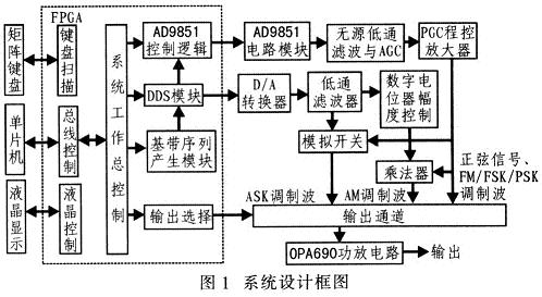
4 System hardware circuit design
4. 1 AD9851 circuit module and control logic
Because the AD9851 operates at a high frequency, it is easy to introduce large noise, so you need to pay attention to the connection between the power supply and the ground wire to reduce noise. In order to avoid high frequency interference, AD9851 and its periphery are realized with PCB board. The circuit is shown in Figure 2. 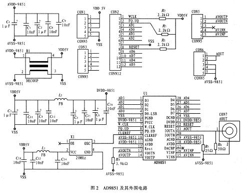
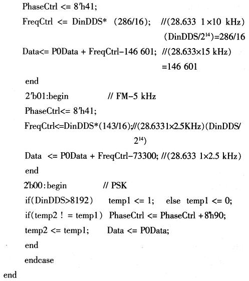
The frequency control word and phase control word writing timing can be parallel or serial, which can be realized by PFGA internal state machine. The FM modulation set by the system is divided into two levels of maximum frequency deviation: 5 kHz and 10 kHz, and the PSK modulation signal is realized by changing the phase control word. The control word and theoretical value are calculated as follows: The output data of the low-band DDS wave table is 14 bits (214 = 16 384). The PSK control word changes the phase by 180 ° when the DDS wave table output value is greater than 16 384/2 = 8 192. Since the AD9851 phase control word is the upper 5 bits, if the 180 ° is changed, the phase control word 8'h90 is changed. The highest output of AD9851 150 MHz corresponds to the frequency control word 32'hFFFFFFFF (hexadecimal), so 1 Hz corresponds to 28.633 1 (decimal). The codes of the modulation mode selection and parameter setting are as follows: 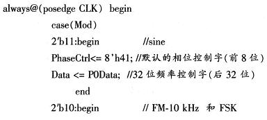
4.2 Passive filter
Filters are generally divided into active and passive filters. Due to the limitation of the operational amplifier bandwidth, the active filter is difficult to meet the filtering requirements in the system band, so the elliptic function filter in the passive filter is used. Design the elliptical low-pass filter with a normalized graph, as shown in Figure 3. Because the passive filter circuit has strict requirements on impedance matching, a special impedance matching part is designed for this purpose. Input impedance matching uses non-inverting amplifiers to achieve isolation. The magnification is adjusted by the potentiometer RP1. If the magnification is too low, it will affect the filtering effect, and if it is too high, it will affect the bandwidth. It is actually about 4 times. The output impedance matching uses an inverting amplifier, because the input impedance of the inverting amplifier is equal to R4, which is easy to achieve impedance matching. 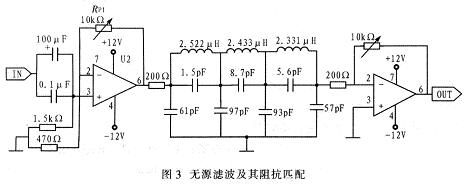
5 System software design
Figure 4 shows the system software design process. The single-chip computer controls the keyboard and display to realize human-computer interaction, including prompt information display, function selection, parameter input, etc., which makes the human-machine interface friendly and easy to operate. 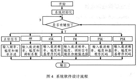
6 Conclusion
The signal output range of the sinusoidal signal generator reaches 100 Hz to 10 MHz, the frequency stability is better than 10-4, the amplitude stability is adjustable, and it can output various commonly used modulation signals, and has instant frequency conversion, flexible control, stable amplitude, The advantages of small size and low cost make the system able to be used as a signal source in various portable fields. 