Measuring the new trend of the industry: with cross-domain knowledge into engineers standard
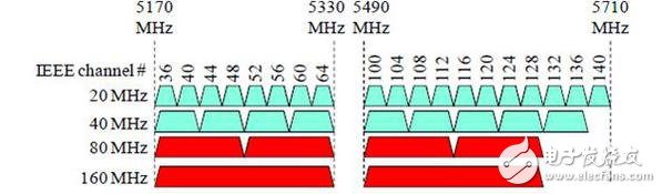
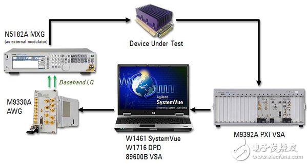
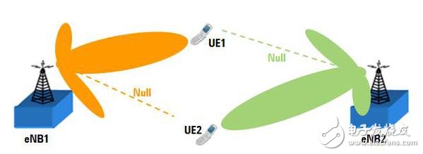
There are thousands of black-headed taxis driven by qualified taxi drivers in London, England. In order to obtain a taxi license, these drivers must pass the exam to prove that they know every street name, every turn, and the route from A to B. Before the exam, they spent a few months training: with maps, bicycles or motorcycles, they kept on the streets to familiarize themselves with all street routes, one-way streets, and quick shortcuts. . This situation is very similar to today's measurement industry trends. The goal of traditional metrology science is to provide data (maps), but to completely ignore the experience and efforts in the process, so this approach has fallen behind. Current and future design and measurement tools need to provide more knowledge than the original measurement data and provide tools that can continue to move toward the next step. In addition, with the rise of versatile products, component and system integration will become more and more common, but the effort and gains of engineers may not be proportional. Take the wireless local area network as an example. The new 802.11ac standard is about to be approved and will significantly improve the network speed and capacity of home and small office networks in the future. The new standard supports wider RF bandwidth, higher modulation density, and more space for multitasking streaming. Not long after, the market will be flooded with millions of new low-cost routers, so if you can save a few cents of material or parts costs, you can significantly reduce manufacturing costs and improve the company's profitability. The RF amplifier is one of the most costly components, and now it needs to perform linear operation over a wider bandwidth (including the split 80+80 MHz non-continuous channel, see Figure 1). Figure 1: Spectrum allocation of IEEE 802.11ac in Europe, Japan and the world In order to reduce costs, manufacturers try to use parts that are cheaper but not sufficiently rigorous, so the output linearity error needs to be corrected at the input. Sounds like it's okay? Since the amplifier has digital I/Q inputs and RF outputs, it is necessary to have knowledge across different fields to make corrections! Digital predistortion technology improves the linearity of the power amplifier by generating and measuring signals that are three to five times wider than the linearized amplifier. Control software can be used to generate the excitation waveform, which is then downloaded to the RF signal generator and input to the power amplifier, which can then be used to capture the response of the amplifier and compare it to the signal from which the predistortion matrix can be established. The predistorted signal is input to the power amplifier and the response is checked. Figure 2 shows the predistortion system required to create a correction matrix. Figure 2: Digital Predistortion System On the other hand, mobile operators have introduced fourth-generation cellular networks based on the 3GPP LTE standard. In order to improve the quality of service, especially at the cell edge, the industry uses a technique called beamforming in the base station transmitter. This technique is well suited for LTE networks in the Time Division Multiple Mission (TDD) mode where the uplink and downlink operate at the same frequency. Beamforming techniques can find interference patterns when the same signal is sent from two or more transmission points located in different spaces. The generated beam can be corrected in real time by transmitting and receiving signals using a linear array antenna of a base station (or eNB) and carefully controlling the relative amplitude and phase weights of the data symbol replicas applied to each antenna component. The pattern and focus on the transmitted energy and the receiving sensitivity in the transmission direction of the specific mobile device (UE). This helps reduce interference when other mobile devices are communicating with neighboring base stations. You must know the location of the UE in the cell to select the best downlink transmit beam. The eNB typically measures the received uplink reference signal directly and estimates the optimal weight accordingly. You can observe these signals in the overall eNB receiver array, which can then be used to calculate the uplink arrival angle (AOA) and decompose the channel characteristics matrix. Figure 3 shows that eNB1 is communicating with the target device UE1, during which eNB1 transmits using beamforming techniques to maximize the signal power in the UE1 direction. At the same time, it attempts to minimize interference to UE2, thus controlling the power zero position in the UE2 direction. Similarly, eNB2 also uses beamforming techniques to increase its UE2 direction of transmission reception and minimize interference to UE1. Figure 3: Enhance cell edge transmission efficiency through beamforming How do I check if the newly developed device supports the aforementioned process? One of the main test challenges of beamforming technology is to verify the beamforming performance of the beamforming on the physical RF antenna array and visualize the results. The purpose of this is to verify the correctness of the eNB RF antenna check accuracy and the baseband coded beamforming weighting algorithm. This shows that system calibration is a key element in achieving excellent measurement accuracy. Figure 4 shows a typical beamforming test system. Gsm Panel Antenna,Gsm 3G Panel Antenna,Adhesive Mount Antenna,Omni Directional 3G Antenna Shenzhen Yetnorson Technology Co., Ltd. , http://www.yetnorson.com