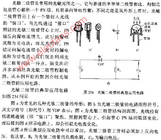
Typical application circuit diagram of photodiode
Here is a typical application circuit diagram for a photodiode. A photodiode is commonly used in light-sensing applications, and its circuit configuration usually involves connecting it in reverse bias to detect light intensity. In this setup, the photodiode is connected in series with a resistor, and the output voltage is measured across the resistor. This configuration allows the photodiode to generate a current proportional to the amount of light it receives. The circuit is often used in devices such as optical sensors, light meters, and automatic lighting systems. Understanding how to properly connect and use a photodiode is essential for anyone working with optoelectronic components. The image below shows a standard schematic representation of such a circuit. High Voltage Resistant Wire,High Voltage Wire,High Temperature Resistant Wire,Silicone Rubber Cable JIANGSU PENGSHEN HIGH TEMPERATURE WIRE CABLE CO., LTD. , https://www.pengshencable.com