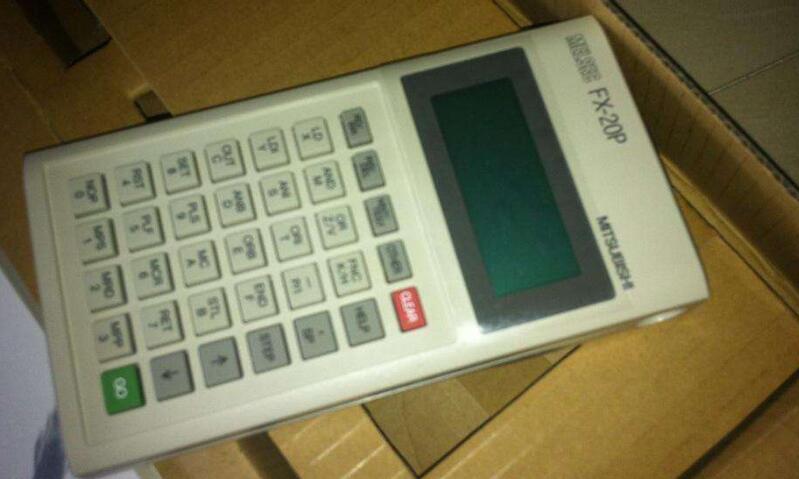
Omron handheld programmer instructions
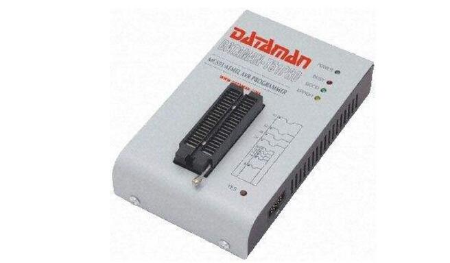
The programmer is a tool for writing data to a programmable integrated circuit, and the programmer is mainly used for programming (or writing) of a chip such as a microcontroller (including embedded)/memory (including a BIOS). The programmer mainly modifies the program in the read-only memory. The programmer is usually connected with the computer and then used with the programming software.
The programmer connects with the computer parallel port (printer interface) through the data cable, independent external power supply, more convenient operation, more stable programming; using the graphical interface under WINDOWS, using the mouse to operate, support Windows ME/98/95/2000 system, With programming instructions, the control program has a friendly working interface, and the various operations on the chip become very simple. Either electronic or computer enthusiasts can easily master it.
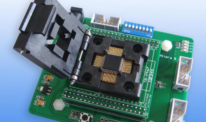
Step 1: Insert the programmed chip (such as the BIOS) in the correct direction into the programming card holder (the chip notch on the card holder).
Step 2: Insert the corresponding cable into the computer's serial port and programmer's communication port.
Step 3: Turn on the programmer's power (power is 12V). At this time, the middle power LED light is on, indicating that the power is normal.
Step 4: Run the programmer software. At this time, the program will automatically monitor the communication port and the chip type. Then from the programming software, call the previously prepared program file (hex file).
Step 5: Then start programming, and then the programmer starts to write the program to the chip. After the programming is complete, the programmer will prompt the programmer to complete the programming. Then power off the programmer and remove the chip.
The basic preparation of the data copy operation of the memory using the programmer is: a computer (the programmer does not have a high requirement for the computer, generally speaking, as long as it can run the Windows 98 operating system), a programmer and a programmer Supporting driver software. The general steps are as follows:
1 Connect the programmer to your computer. Different programmers and computers are not connected in the same way. Some programmers are connected to the computer parallel port (printer interface), some are connected to the computer's serial port (COM1 or COM2), and some use the USB interface (such as RF910 ). In terms of speed, the USB interface is the fastest and the serial port is the slowest.
2 Install the driver software that is provided with the programmer to the computer and make related settings to the programmer as required.
3 Run the programmer driver software. The figure shows the running interface of the RF910 driver software. Select the memory model.
4 Operate the programmer driver software to read the data stored in the computer as a data source.
There are two ways to obtain the memory data source: The first is to find a normal display of the same type as the repaired faulty machine, remove the memory, insert it into the programmer, read out the data, and save it to the computer. The second is to directly use the memory data already stored in the computer (this can be a backup of the data that was previously done by the manufacturer, data provided by the manufacturer, or data downloaded from the Internet).
5 Insert the blank memory (or used memory) into the programmer, operate the programmer driver software, and the programmer writes the normal data into the blank memory.
6 Replace the new memory with the data written to the faulty machine.
1, the programmer's panel
Programmer Mode: There are three modes for the programmer to choose from
PROGAM mode - CPM1A is in a stopped state, at which point user program can be written, modified, cleared of memory, and program checks are performed on the program.
MONITOR mode - CPM1A is in operation and the input and output are handled in the same manner as the operating mode. In this mode, the monitoring of the operating status of the CPM1A, the forced ON/OFF of contacts, the setting of the timer/counter/modification of the current value, the modification of the current value of the channel data, etc. can be realized. Mainly used for system test run adjustment.
RUN mode - Used for the operating state of CPM1A. In this mode, operation monitoring of CPM1A can be performed, but the programmer cannot be used to modify the forced ON/OFF of the contacts and the timer/counter set value/current value.
* When the programmer is not added to the CPM1A, the PLC is automatically in the RUN state after the power is turned on. When the programmer is added to the PLC, the working mode of the PLC depends on the position of the working mode selection switch on the programmer. MONITORRUNPROGRAM
FUN function keys
SFT basic instruction keys
NOT basic instruction key
SHIFT shift key and upshift function key up function
AND basic instruction key
OR basic instruction key
CNT basic instruction key
TR data area key * EM data area key
LR
AR data area key
ER
LD basic instruction key
OUT basic instruction key
TIM basic instruction key
EM data area key
DM
CH data area key *DM
CONT Data Area Keys#
EXT foreign key, tape drive storage
CHG Modify Key T/C Current Value Modify .DM Content Modify
SRCH search key, search instruction or bit position
Force ONDEL delete instruction key during SET debugging
MONTR monitor button, monitor channel or bit status
Strong RESET debugging
OFFINS insertion instruction key
Address increase key
2, the function of the programmer
1) memory clear
User program, PLC system setting, data clear of each relay, T/C, DM
2) address establishment
Create program memory address during program input, read, insert, delete, etc.
3) Program input
Performs program input, command modification, and set value modification
4) Program readout
Read the contents of the program memory, and read and write the contact status in the operation and monitoring mode
5) Program check
Check if the content of the program complies with the programming rules. If there is any error in the program, the address and contents of the error will be displayed.
6) Instruction retrieval
Retrieve the instructions in the program
7) Contact search
Retrieving the contacts of each relay and timer/counter specified in the program
8) Instruction insertion
Insert the instruction program in the middle of the original program
9) Instruction deletion
Delete some instruction programs in the original program
10) Bit, Number, Word Monitoring
Monitor the data contents of relays, timers, counters, and data memory
11) Multi-point monitoring
Simultaneous monitoring of 6 points or channels. You can only display 3 points at a time on the monitor
12) Differential monitoring
Detects the edge state when a contact is OFFON
13) Binary monitoring
Monitoring of each relay, data memory in channel units, displayed in binary 16-bit format
14) 3 word monitoring
Continuous 3 channels simultaneous monitoring
15) Signed decimal monitoring
Convert the hexadecimal number represented by two's complement in the channel to a signed decimal number.
16) Unsigned decimal monitoring
Convert the hexadecimal numbers in the channel to unsigned decimal numbers.
17) 3 word data modification
Aggregate modification of continuous 3 channel data
18) Modify T/C setting 1
Modify timer/counter settings
19) Modify T/C setting 2
Modify the timer/counter settings in fine-tune
20) Modify the current value 1
Modify the current value of hexadecimal 4-inch, 10-decimal 4-inch data
21) Modify the current value 2
Modify channel data to binary 16-bit data
22) Modify the current value 3
Change the decimal value of the channel being monitored to a signed decimal number in the range of -32767 to 32767. The contents of the specified channel are automatically converted to signed hexadecimal numbers (in binary 2's complement format)
23) Modify the current value 4
Change the decimal value of the channel being monitored to an unsigned decimal number in the range 0 to 65535. Changing to hexadecimal data is automatic
24) Forced set/reset
Force the relay, timer/counter contact to ON (set)/OFF (reset)
25) Clear Forced Set/Reset
Restores the status of all contacts that were force set/reset
26) Read out the scan time
Displays the average scan time of the execution program
27) Read/clear faults and messages
Read out faults and messages. Clear the error message.
28) Buzzer sound on/off switch
Buzzer sound switch when switching programmer button
29) Hexadecimal and ASCII display conversion
When monitoring the data memory, the 4-bit hexadecimal display format is converted back and forth to the alphabetical display format.
Second, the use of programmerAfter the PLC is powered on, the PASSWORD “Password†appears on the programmer. After pressing the CLR MONTR button, the password disappears. Press the CLR button again and the address 0000 is displayed on the screen. Then you can perform various operations.
1, memory clear
Clear memory operations must be performed in PROGRAM mode.
1", full memory clear
All data in the program, relay, timer/counter, and data memory in the memory is cleared. Press Clear CLR in sequence to set SET NOT to reset RESET to monitor the MONTR key. Before pressing the MONTR key, the user is prompted to clear the word 00000MEMORYCLR? HRCNTDM
2", partially cleared
If the user needs to retain the program before the specified address or the contents of HR, CNT, and DM need to be reserved, do not directly press the MONTR button while pressing the last program address of the reserved program segment and want to retain The area (HR, DM, or CNT) is pressed again after the MONTR key, the operation should meet the user's retention requirements, only the part that needs to be cleared is cleared.
2, address establishment
In any mode, after pressing the CLR MONTRCLR button after the PLC is powered on, the screen immediately
The address 00000 is displayed. To change the address to 01000, just press 01000 five digits on the keyboard. To display the program contents of the address, press the key or key again.
3, program input
In the PROGRAM state, operations such as program writing, command modification, and setting value change can be performed. Use the command key and the number key to input the instruction. After inputting one instruction or one data, you need to press the WRITE key once. At this time, the address is automatically incremented by 1 and the instruction content of the next address is displayed.
If the instruction has multiple operands, after pressing the WRITE key after inputting the instruction, the address will not increase by one. The contents of the next byte will be displayed on the display. Press the WRITE key after the input is completed, and the program address will be incremented by one.
When the input instruction is a differential type instruction, after the input instruction (double-byte instruction before the input operand), press the NOT key to display the differential @ indicated on the screen, if the instruction is a normal scan instruction, press again The NOT key returns to the normal scan type.
The application command is written after the function key FUN is pressed and then the FUNNO (function code) of the application command is specified with the number keys, and then the WRITE key is pressed to write.
1 Write hexadecimal, BCD code constant when CONT / # key, directly press the number key, press WRITE key to write; 2 and to write the channel address, press the number key directly after pressing WRITE key to write;
3 Input the initial setting value with unsigned decimal number. After pressing CONT/#SHIFTTRNOT, write the unsigned decimal number (setting range is 0 to 65535) and press WRITE to write. (If you make a mistake, press CLR to return to the previous state and re-enter the correct value.) To return to the hexadecimal display, press SHIFTTR.
4 To write a signed decimal number, press CONT/#SHIFTTR to enter the set value with a signed decimal number (when inputting a positive number, press SET "represent +" and the numeric keys, enter a negative number Press RESET "representing -" and number keys) and press WRITE. To return to hexadecimal status, press SHIFTTR button.
4, program read
Program read operations can be performed in three modes of RUN, MONITOR, and PROGRAM to read the contents of the user memory.
Set the address that needs to be read. After pressing the key or key, the address will continue to increase or decrease by 1 using the key or key. The user program can be read out.
5, program inspection
This can only be done in PROGRAM mode to confirm that the content of the user program complies with the programming specifications. When there is an error in the program, the address and contents are displayed. Press CLRSRCH button, the display will display the check level prompt, and then enter the check level (optional 0 ~ 2), if the program is wrong, the error address and error content are displayed on the screen, and each press SRCH button, it will Displays the next error address and error contents of the program. If the program has no errors, XXXXXPROGCHKEND(001)0.03KW is displayed
Where XXXXX represents the address of the END(01) instruction of the program.
The program's errors are divided into A, B, C three, check 0 to check A, B, C type errors; check 1 to check A and B type errors; check 2 to check A type error. Program Error Table Level Error Message Cause and Action A
The contents of the program have been destroyed. Please re-write the program
NOENDINSTR
There is no END instruction in the program. Please write the END (01) instruction at the end of the program.
CIRCUITERR
Program logic error, generally the number of logic start (LD instruction) and program block operation (ORLD and ANDLD instruction) is inconsistent, please check and correct the program
LOCNERR
The displayed instruction is in the incorrect area. Please confirm the use of the instruction and correct the program.
DUPL
No. Repeat error, the currently used subroutine number or JME number has been used in the program. Correct the program, use a different subroutine number and JME number.
SBN UNDEFD
The called subroutine number does not exist, confirm and modify the program
JME UNDEFD
JME NO corresponding to JMP NO does not exist, a transfer program has no tail, confirm and modify the program
OPERAND ERR
The specified variable operand data error, check the operand data range of each instruction and correct it
STEP ERR
Stepping error, check and modify program B
IL—ILC ERR
The IL-ILC instruction is not used in pairs and is not necessarily a true error. Check to see if the program is wrong
JMP-JME ERR
JMP-JME is not used in pairs, check and confirm if the program has this error
SBN—RET ERR
The displayed instruction is incorrectly used (SBN or RET), the same subroutine number is used in more than one SBN, correct error C
JMP UNDEFD
A given JMP instruction does not correspond to JMP, check and correct
SBS UNDEFD
A defined subroutine has not been called. It may be a common phenomenon
COIL DUPL
The same output coil is used multiple times to check and confirm if the program is actually wrong
6, instruction retrieval
This operation can be completed in the RUN, MONITOR, PROGRAM mode.
To retrieve an instruction in a program, use the instruction search. Press the CLR key and type to start
After searching the program address, type the instruction to be searched, and then press the search key SRCH. The programmer displays the content of the instruction to be retrieved and its address on the display screen. Press the key to display the instruction's operand (for For multi-operand instructions). To continue to retrieve the instruction, press SRCH repeatedly until the END instruction or the last address in program memory is retrieved.
7, contact search
The contacts used to retrieve the programs that have been stored in the memory can be operated in RUN, MONITOR, or PROGRAM modes, and the status of the contacts in the RUN and MONITOR modes can be displayed.
Press the CLR key, input the starting address to be searched, press the SHIFT CONT/# key and the contact number to be searched, and then press the SRCH key. At this time, starting from the starting address, the first one contains the contact The number command is displayed on the screen. Press the SRCH button again to continue retrieving the contact until the END command.
8, instruction insertion
Can only operate in PROGRAM mode. Insert an instruction in the existing original program.
First use instruction readout or instruction search to find out the address of the instruction to be inserted (find the next instruction to insert the instruction), then type the instruction to be inserted, then press INS (the prompt INSERT is displayed on the display screen) Then press the key, the instruction is inserted,
To insert a multi-byte instruction, after the above operation, input the operand continuously and press WRITE.
9. Instruction deletion
Operates in PROGRAM mode to delete an instruction in a program. First read out the program to delete the address, then press DEL (the prompt is displayed on the screen
DELETE? ) Then press the key, the original program will be deleted. When multibyte instructions are deleted, the operands are also deleted.
10, Bit, Number, Word Monitoring
Can operate in RUN or MONITOR mode. You can monitor the status of I/O and internal relays, special auxiliary relays (232~255CH), AR, HR, and LR, and monitor the T/C status and contents. 1", dynamic T/C monitoring
Used to monitor the current value and status of the T/C. Press the CLR button to clear the display, press the TIM or CNT button, and then type the T/C number you want to monitor. Then press the MONTR button to see the dynamic change of the corresponding T/C on the display. Use the or key to change the T/C number.
Waterproof Electrical Box,Waterproof Junction Box,Waterproof Cable Joint Box,Weatherproof Pvc Junction Box
FOSHAN SHUNDE LANGLI HARDWARE ELECTRICAL CO.LTD , https://www.langliplastic.com