Research on self-healing ring network of optical fiber CAN bus
The CAN bus is a serial data communication protocol developed by the German Bosch company in the early 1980s for solving many data exchanges in automobiles. Because of its excellent characteristics, the CAN bus has become one of the most promising fieldbuses currently recognized. The transmission medium of CAN bus can be twisted pair, optical fiber and coaxial cable. At present, the twisted pair CAN bus has been widely used, and various technologies have matured. The twisted pair CAN network is easy to implement in technology, low in cost, and has a certain ability to suppress environmental electromagnetic radiation. But when the working environment is particularly complicated, its anti-interference ability is not very satisfactory. If the situation is more complicated at the electric car site, the onboard electrical system will generate strong electromagnetic interference, which will cause the twisted pair CAN network to not work properly. Compared with twisted pair and coaxial cable, the superior performance of optical fiber-strong anti-EMI ability has attracted people's attention. To further improve the performance of the CAN network, optical fiber should be used as the transmission medium. Due to the short transmission distance of the vehicle-mounted local area network, and in order to reduce the cost of the vehicle-mounted optical fiber CAN network, plastic optical fiber (POF) can be used as the transmission medium. Plastic optical fiber has low cost, easy connection, good windability and light weight in high-speed and short-distance communication transmission, so the cost of networking is low. BMW Germany used the 50m POF to build the in-vehicle local area network in the most advanced new car "BMW7 series" which was launched in March 2002. The optical fiber CAN network is an industrial bottom-layer control local area network. Its topology is the same as the common local area network. The basic topology has a bus shape, a ring shape, and a halo shape. In a fiber-optic single-loop CAN network, the delay of the device will cause the loop signal to self-excite, causing the ring CAN network to be blocked (or called deadlock). In order to comply with the protocol of the CAN bus controller at the link layer, an optical fiber CAN single-loop network dedicated logic control unit LCU should be designed. The function of this unit is to realize the sending and receiving control of CAN bus data, that is, the master node does not forward the received data. When the data is returned to the original sending node along the fiber ring, it is immediately deleted; the slave node forwards the received data. At the same time, the self-excited phenomenon of the ring fiber CAN bus network can be eliminated to ensure that the ring network is not blocked. In a Q fiber single-ring network, the failure of a node or link may cause the network to be paralyzed. In order to improve the survivability of the optical fiber ring network, an optical fiber double ring self-healing network with self-healing function should be formed. 1.1 Fiber self-healing ring structure The optical fiber self-healing ring CAN network is shown in Figure 1. The network has two fiber loops—clockwise and counterclockwise. The CAN controller SJAl000 of each node is connected to the dual-ring optical network through an interface circuit. The interface circuit is a complex programmable logic device (CPLD) EPM7128S produced by Altera Corporation. It consists of two optical transmitters LEDR and LEDL, and two optical receivers PINR and PINL. 1.2 The function of the interface circuit The function of the optical fiber self-healing ring CAN network interface circuit is: (1) When the optical fiber double-loop communication is normal (as shown in Figure 2 (a)), the right end optical transmitter LEDR of each node transmits the data of the left end optical receiver PINL, and the signal is smooth Clockwise transmission; Similarly, LEDL transmits PINR data, and the signal is transmitted counterclockwise, that is, the transmitter selects the opposite side to forward the data. (2) When a single fiber fails (as shown in Figure 2 (b)), the downstream C node interface circuit realizes loopback. Since the left optical receiver PINL has no signal, the right optical transmitter LEDR selects the same side optical receiver PINR data forwarding. (3) When two optical fibers between any nodes fail (as shown in Figure 2 (c)), such as when the optical fiber between BC nodes is cut, then the two nodes B and C are connected to the fiber cutting point to perform the loopback function. At this time, the signal AC from A to C first passes through the clockwise ring to B, and then passes through A and D counterclockwise to reach C. The signal CA is still transmitted through the clockwise ring. This self-healing function ensures that the continuity of the ring can be maintained in the event of a fault. After the fault is removed, the reverse switch automatically returns to the original position. (4) Realize the node CAN controller data selection and reception. The principle is: for the clockwise and counterclockwise data received by each node, select the data that arrives first in PINL and PINR to receive. (5) Realize the selective transmission of node data. The principle is: when the bus is idle, select the TX of the CAN controller at the local node to send data, which can eliminate the self-excited phenomenon of the ring fiber CAN bus network and ensure that the ring network is not blocked; when the local CAN controller is the receiving node , Select the opposite side data transmission; when the CAN controller of this node is the receiving node, and the opposite side fiber channel fails, then select the same side data transmission. (6) Identify the start and end of each channel frame, identify whether the bus is idle, and whether the network is faulty. If it is judged that there is a data frame being transmitted in the left photometric receiver PINL, the left transmission data flag flag_l and the network communication status flag sync_l are generated. 2 Interface circuit design The self-healing function and transceiver control function of the optical fiber CAN self-healing network are realized by programmable logic devices (ALTERA EPM7128SLC84-15), and the programming adopts VHDL language. The following is a detailed introduction. 2.1 Input and output port settings Figure 3 is a schematic diagram of the I / O port of the interface circuit CPLD. Among them, the input and output pin_l, led_l, 1ed_r, pin_r are connected to the optical / electric conversion module PINL, LEDL, LEDR, PINR: txd, rxd are connected to the data transmitter TX and receiver RX of the CAN spammer respectively; flag_txd = 1 It means that the CAN controller TX0 of this node is sending data frames; flag_l = 1 means that the left channel is sending data frames; flag__r = 1 means that the right channel is sending document frames. sync_l is the left network communication status flag, and sync_r is the right network communication status flag. When the left channel is normal, output sync_1 = "l", driving network status LED D_sl is on; when the right channel is normal, output sync_r = "1", driving network status LED D_sr is on; if the network status LED D_sr or D_sl Off, indicating that the corresponding Fibre Channel on the network has failed. When the CAN controller of this node selects left channel data reception, the output terminal rx_l / r is high level; when the CAN controller of this node selects right channel data reception, the output terminal rx_l / r is low level. The input terminal reset is the reset terminal, and the low level is effective; clk0 is the clock input terminal, and the frequency of the input clock is 20MHz. CPLD is the self-healing interface unit of the control ring network. The control circuit consists of a frequency divider, a central state machine, a sender data selector, and a receiver data selector, as shown in Figure 4. 2.3 Frequency divider The communication interface CPLD clock frequency is 20MHz. In the optical fiber CAN self-healing ring network, each node CAN controller SJAl000 and CPLD interface use independent working clocks. In order to synchronize the signal of the flag generated by the state machine with the data transmission of the CAN controller to ensure that the switching of the two data selectors and the data transmission are synchronized, the clock of the state machine should be correctly selected. In this paper, the CAN network data transmission baud rate is 125kbit / s, status. The rate of the machine clock rxclk is designed to be 8 times the baud rate of data transmission, that is, 1Mbit / s, to ensure that the data can be read many times in a CAN data bit period, and improve the anti-interference ability. Therefore, the function of the frequency divider is to generate a clock frequency of 1 MHz. 2.4 Central state machine According to the CAN 2.0B protocol, the CAN network data frame is composed of 7 different bit fields, namely the frame start, arbitration field, control field, data field, CRC field, response field, and frame end. The length of the data field can be 0 to 8 bytes. The start bit of the frame is a dominant bit low power? "0"; the end of the frame is a sequence composed of 7 recessive bits "1"; in the transmission of the data frame, the bit filling technology is used to encode to ensure the data frame bit 5 consecutive "1" or "0" will not appear in the stream. The central control state machine is the core unit of this design. The function of the central state machine is: (1), detect the start and end of the CAN data frame, and generate the corresponding transmitted data flag signals flag_txd, flag_r, and flag_l. (2) Generate network communication status flags sync_r and sync_l. The central state machine consists of: three state machines: the CAN controller state machine of this node, the left channel state machine and the right channel state machine. They separately judge whether each channel (TX, PIN_L and PIN_R) has data transmission. The following explanations of the state machines in each place take the CAN controller state machine of this node as an example. When the state machine is in S5, after each clock cycle of rxclk (1MHz), the state machine state advances further (S6, S7, S8, S9, S10, S11, S12, ..., S58, S59, S60); 8 clock cycles, one detection of the data bits on the CAN bus (S12, S20, S28, S36, S44, S52, S60) to ensure that each detection is in the center of the data bit (bit cycle). When txd = "1" is detected seven times in a row, "1" is detected to indicate the end of "frame", and the transmission data flag is reset flag_txd = "0", waiting for the next frame start; otherwise, the state machine returns to state S5, Wait for the end of the frame. The network communication status sync_r, sync_l is an important basis for ring network self-healing. As described above, when the left and right channels send the data status flag flag = "1", the network communication status of each channel is sync = "1", and the network status LEDs D_sr and D_sl are on; when the frame ends, flag = "0" , Start the network communication state count group count, its clock is rxclk = 1MHz, when the counter is 30000 (30ms), sync = "0", the network status LEDs D_sr and D_sl are off. This means that after a certain data frame is transmitted, if If the start of other data frames cannot be detected, the network is faulty. If the start of the data frame can be detected within 30ms (flag is set), the network communication status flag continues to be "1". Time when the counter reaches full value It should be the shortest time interval between frames. 2.5 Data selector The function of the sending data selector and the receiving data selector is to realize link establishment (that is, channel selection). To ensure the normal operation of the network, the CAN network delay should be less than a data width (bit period). To keep the link setup time as short as possible, the highest clock frequency (20MHz) is used to control the two data selectors. In the transmission data selector, CPLD detects three channels of data txd, pin_l, pin_r. The data of each channel has different priority. The priority setting is: when the node sends data (txd = "0" or flag_txd = "1"), the left and right channels send CAN control tanning ⑺ cast 薚 X data, that is, led_r = txd, led_l = txd. If the node does not send data, it chooses to send data according to sync_r and sync_l. When the left and right channels are normal, select the opposite side to send data. Led_r = pin_l, led_l = pin_r. If a channel fails, the opposite side data cannot be received, then choose For data sending on this side, led_l = pin_l, led_r = pin_r. According to this, not only the network self-healing is realized, but also the ring network blocking problem is eliminated. The optical fiber CAN self-healing ring network is built in the electric vehicle. The plastic optical fiber is used as the transmission medium. The plastic optical fiber has a low-loss window in the visible light region. The optical / electric conversion module with an operating wavelength of 650nm (red light) is selected-manufactured by Agilent. Optical transmitter HFBR-1528 and optical receiver HFBR-2528. Each node CAN control unloader uses SJAl000 or TMS320LF2407 DSP chip with CAN controller to form 4 node vehicle-mounted optical fiber CAN self-healing ring network. The data transmission rate of the CAN network is set to 125kbit / s. When a certain channel is set to fail, the network can realize the self-healing function shown in Figure 2 (b); when two optical fibers between any nodes are set to fail, the network can Realize the self-healing function shown in Figure 2 (c). When the CAN node fails, the interface circuit can still ensure the normal operation of the double ring network; but when the interface circuit fails, it will cause this node to leave the bus, and other nodes realize the network self-healing, forming a single ring network. Observe the waveform through the oscilloscope, the sending node competes to send data through the bus; the receiving node can send an answer signal to the bus; the time for the node data to return to the original node through the 4-node fiber CAN self-healing loop is less than 100ns. After testing, the channel failure network self-healing time is 301ms
Qunsuo aims at providing our customers high qualified Industrial Rugged Pda. In order to meet customers using environment, our PDAs all pass IP65 certification. With the stable quality of our Handheld Android Pda, we gain many reliable customers, help many customers provide IT solutions. If you are also looking for reliable PDA manufacturer partner, Qunsuo will be your good choice. Welcome to contact us for more details!
Industrial Rugged Pda Android Pda Europe,Pda With Desktop Charger,Rugged Handheld Pda Honeywell,Handheld Barcode Scanner Pda Shenzhen Qunsuo Technology Co., Ltd , https://www.qsprinter.com
figure 1
1 Overall design of optical fiber self-healing ring CAN network
figure 2
2. 2 CPLD functional structure 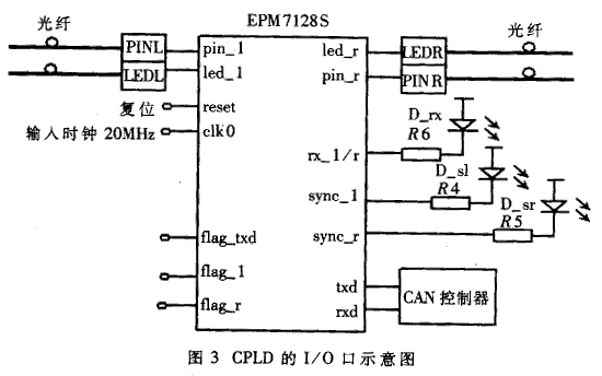
Each state machine sets 61 states, namely idle, S1, S2, S3 ... S60. When the bus is idle, the state machine is in idle state idle. At this time, the upper edge of rxclk comes. When txd = 0 is detected, the state machine turns to S1 and sends the data flag setting signal flag_txd = "1"; when the second upper edge, The state machine turns to S2 unconditionally; when the third upper edge, the state machine turns to S3 unconditionally; when the fourth upper edge, the state machine turns to S4 unconditionally; when the fifth upper edge comes, this is the central position of the data bit, the data is stable, right The data is read again. If the condition of txd = "0" still holds, it means that the start of the frame comes, and the state machine turns to S5; otherwise, flag_txd = "0", meanwhile, the state machine turns to the idle state idle, waiting for the arrival of the start of the frame. 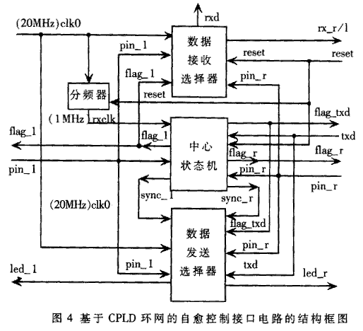
In the receive data selector, set the left channel as the preferred receive channel; when the left channel data does not arrive (flag_l = "0 '') or the left channel fails, without human intervention, the right channel is automatically selected to receive. According to this Realization of receiving optimization (selection of priority arrival channel data reception) and self-healing function of optical fiber CAN bus double ring network. 