Design scheme of portable insulin pump
The insulin pump is a portable medical device. In the device in Figure 1, the insulin pump must also include comprehensive self-test and fault display functions, which requires additional circuits and the use of devices with self-test functions. Manufacturers of battery-powered insulin pumps have made considerable progress in reducing power consumption and extending battery life. For today's insulin pumps, the battery life or charging life can reach 3 to 10 weeks. Many insulin pumps on the market use single AA or AAA alkaline or lithium batteries. Disposable (non-rechargeable) batteries are common, but rechargeable batteries can be used to reduce long-term costs for patients. Because rechargeable batteries have less power than disposable batteries, they have a shorter battery life between charges.
MC Flex Outdoor Rental LED
Display
Advantage of Outdoor Rental LED Display P3.91 P4.81 P5.95
Outdoor Rental LED Display Outdoor Rental LED Display,Outdoor Full Color Rental LED Display,Outdoor Rental LED Screen Display,Outdoor Curtain LED Display Shenzhen Macion Optoelectronics Technology Co.,Ltd. , https://www.macion-led.com
Portability
Insulin pumps are wearable devices, so they must be very small and light (Figure 2). Its volume is usually about 2 & TImes; 3 & TImes; 0.75 inches (5.7 & TImes; 7.6 & TImes; 1.9 cm) and weighs 2 and 4 ounces (57 grams and 113 grams). These shape requirements allow designers to prioritize their size and power consumption when choosing a device. 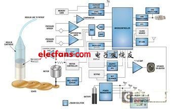
Figure 1: Functional block diagram of the insulin pump system; Meixin can provide solutions in blue.
To save space, system designers need highly integrated solutions and very small packages, such as: chip-scale packaging (such as the US UCSP package) and wafer-level packaging (WLP). To keep the battery volume as small as possible, designers must reduce energy consumption and increase efficiency as much as possible. If possible, turn off those circuits that are not in use at any given time, and then supply power to them when working.
The core of the system is a highly integrated low standby power microcontroller-such as Maxim's MAXQ2010, or similar microcontrollers of other manufacturers. The 16-bit microcontroller MAXQ2010, when operating at 1MHz and 2.7V, consumes only 1mA, and the shutdown mode consumes only 370nA. This low power consumption feature is essential for extending the working life of the battery in the insulin pump. Like most microcontrollers, MAX2010 includes USART, timer, 64kB flash-based program memory, 2kBRAM, some general-purpose I / O pins, 312.5k samples / second 12-bit successive approximation ADC with reference voltage, 160-segment LCD Controllers and other resources. It can also quickly wake up from sleep and stop modes, enabling the insulin pump to better and faster serve user needs. 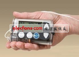
Figure 2: A typical battery-powered insulin pump.
Insulin pump subsystem
Insulin is measured in "units" and there are 100 units per cc (that is, mL, milliliter) (assuming the standard U-100 concentration method is used). This means that one unit is 10 μL (microliter). The magnitude of the basal metabolic rate is at the unit / hour level. It should be controlled and adjusted every 3 to 10 minutes, and a single dose is a few units. A typical insulin-carrying container has a capacity of 200 to 300 units.
Due to its ultra-low flow rate, the motor driving the gear pump is decelerating, usually using a screw to push the container piston very slowly, for this reason the motor has to turn a lot. Therefore, only a rough angle measurement of the motor is required. Most major insulin pump manufacturers use optical encoders and DC motors, although stepper motors are also available. Other possible methods include using MEMS-based pumps to make the system as small as possible, or using pressure pumps to remove the motor and remove the piston-based reservoir.
Pressure sensors are used to ensure normal operation and detect blockages. Based on silicon strain gauges, these sensors can provide millivolt-level signals instead of microvolt-level signals provided by bonded wire strain gauges. The strain gauge uses a typical bridge configuration to provide a differential signal at a common-mode voltage of approximately half the supply voltage.
The design will use an ADC with a differential programmable gain amplifier (PGA) input or an ADC with an external differential or instrumentation amplifier for signal modulation integrated into the microcontroller. Because pressure readings are only used to display normal operating conditions and are not used to calculate medication, no precise pressure measurement is required.
Subsystem power supply
Insulin pumps usually use a boost regulator to raise the lower voltage (nominally 1.5V) of a single alkaline battery to 2V or higher. To achieve the longest battery life, these boost regulators should work at the lowest input voltage possible. The operating voltage of the voltage regulators of Meixin and other manufacturers can be as low as 0.6V, and the starting voltage can be as low as 0.7V, thereby maximizing the battery life.
The MAX1947 is such a boost DC-DC converter with an input voltage range of 0.7V to 3.6V. Its 2MHz switching frequency and current mode control method reduces the size of the component, can achieve more than 94% efficiency, and has a fast transient response. It integrates all necessary switches (power switch, synchronous rectifier, reverse current blocker) to minimize the size of the solution. During shutdown, the True Shutdown? Circuit allows the load to be isolated from the battery to maximize battery life.
For devices that require strict regulation of the supply voltage, it may be necessary to step down the boosted voltage discussed above. For ultra-low power applications, linear regulators may be more efficient because they do not have the switching losses of switching power supplies. A buck regulator with skip mode has good light-load efficiency; but the low-dropout linear regulator (LDO) solution is smaller in size, which is very important for insulin pumps. The efficiency of LDO is very close to the ratio of VOUT / VIN, so if the input voltage is a fixed voltage slightly higher than the LDO dropout specification, its efficiency can be very high.
If the motor drive needs voltage regulation, the system designer will use a switch-mode converter. To reduce size and weight, the operating frequency of these converters should be as high as possible. When multiple power outputs are required, a power management IC (PMIC) can be used to save space.
In view of size restrictions and the widespread use of disposable batteries, insulin pumps do not include battery chargers. Since disposable batteries do not have a fuel gauge, battery life indication generally relies on simple battery voltage measurement and sometimes temperature measurement. These voltage and temperature readings are sent to the ADC for digital processing. The microcontroller will process the data and use a look-up table to determine the remaining battery capacity within three or four divisions. Then it will drive a display, usually a battery symbol with a remaining battery indicator. When the last frame is left, the insulin pump will issue a low battery warning.
Programmability and control options
As mentioned earlier, users can use a complex combination of options to set their basal metabolic rate and bolus dose as needed. These settings can be completed with a simple interface such as few user input buttons. The user can also set reminder information to help manage the insulin infusion dose.
The display generally uses a monochrome, custom character backlit liquid crystal display (LCD), although some pumps also use a color screen. The display provides insulin dose, basal metabolic rate, battery availability time, time and date, reminder information and system alarm conditions (eg, blockage or low insulin inventory). Self-test and power-on display are FDA requirements, so designers need a driver with built-in self-test function. It is usually necessary to give a visible and audible prompt response to the user's touch input.
Newer insulin pump products include continuous monitoring displays. For these systems, there is a separate continuous monitor with a wireless transmitter that measures blood glucose levels and reports the data to the pump that supports the sensor. In response, the pump will display the historical trend information of glucose in a graphical chart to help calculate the insulin dose.
Self-check to ensure that the device is operating normally
All insulin pumps must perform a power-on self-test (POST) to meet FDA requirements. This includes the detection of all key processors, key circuits, indicators, displays and alarm functions. Some POST operations may require user observation, but additional circuits are required to implement self-tests to reduce the risk of undetected failures.
For example, some models of equipment use a safety monitoring processor to monitor the performance of the main processor and issue an alarm when unexpected behavior is detected. Another simple way to self-test is when the light-emitting diode (LED) turns on and off, monitoring the current passing through. If the current is not within the acceptable range, it indicates a fault. Watchdog timer (WDT) is perhaps the most common self-test method. Usually a microprocessor monitor with WDT function is used to ensure that the processor executes the correct code and does not run away. In medical equipment, it is generally not desirable to integrate the monitor and the microprocessor on the same chip, because this will prevent the monitor from the transient conditions that can cause the microprocessor to fail.
In order to ensure that the insulin pump works normally during the use of the patient, the function of the monitor is critical. The microcontroller must remain in reset until all power supply outputs are within tolerance and stable. The voltage monitor monitors the power supply for undervoltage and overvoltage conditions. It is necessary to monitor the motor load and detect the motor stall (stall). (Motor stalling is a key fault, and the highest priority alarm should be issued.) To digitize sensor data such as temperature, motor load, insulin line pressure, and battery voltage, an ADC integrated in the microprocessor or externally connected is required.
Alarm and I / O options
In order to warn the user based on detected faults, a certain time has passed, a warning has been triggered, etc., the insulin pump needs a clear alarm mechanism. In remote blood glucose monitors and insulin pump systems, a single LED can be used as a visual indicator. A flashing green LED usually indicates normal operation, and a red LED emits an alarm or warning signal.
The audio buzzer must include a self-test function, and the buzzer self-test can be achieved in two ways, direct and indirect. 1) Direct mode: embed a microphone near the speaker to detect whether the audio output of the speaker is at a normal power level; 2) indirect mode: monitor whether the speaker impedance is within the specified range. Designers usually use a series of operational amplifiers, comparators, audio amplifiers, microphone amplifiers and other devices to implement alarm and self-test functions. An audio digital-to-analog converter (DAC) can be used to generate a unique alarm output.
Newer insulin pumps may also include an eccentric rotating mass (ERM) motor to achieve vibration alarms. ERM motor drivers are not critical, but some types of amplifiers or voltage regulators may be used. When installing the battery, the ERM can be self-checked by briefly turning on the power.
All insulin pumps must pass the IEC 61000-4-2 Electrostatic Discharge (ESD) requirements, either by using a circuit with built-in protection or by adding an ESD line protector to the exposed circuit. Maxim provides many interface components with such built-in strong ESD protection capabilities and independent ESD diode arrays.
Because of the importance of proper insulin dosage, insulin pumps usually record all activities and program changes and time stamp them. In order to realize these functions and timer alarm, a real-time clock (RTC) is needed.
Many insulin pumps have data ports to support uploading data to computers and downloading firmware upgrades. This allows historical files to be integrated into the application and sent to medical staff to help implement insulin therapy. USB is a commonly used interface. The interface should include functions such as ESD protection, current limiting, and logic level conversion of the memory card.
In addition, an RF interface can be added to the insulin pump to link the pump to the continuous blood glucose monitor or the host computer-the blood glucose monitor can send data about the blood glucose trend to the pump; the host computer can download insulin pump activity from the pump Logs, historical data on glucose trends, or even upload an update command to the insulin pump. This wireless interface can be implemented using Bluetooth or an unlicensed ISM band transceiver.
1, Outdoor high resolution and high
brightness, smallest pixel in the world
3.91mm, unequalled image quality in outdoor environment.
2, Ingress protection reaches to IP65, weather
proof and dust proof.
3, High brightness uniformity and color
uniformity (≥95%)
4, Super thin and light with die-casting
aluminum cabinet design.
5, Good performance: anti-UV and anti-oxidation.
6,Large viewing distance: 140° in horizontal,
140° in vertical.
7, Excellent flatness and no splicing gap
between modules
8, Quick installation and removal with facile
connection lock