Why does the op amp oscillate?
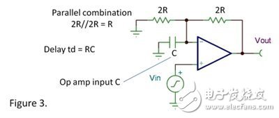
Although the Bode diagram is a very good analysis tool, you may not have found it too intuitive. Bode plots are a visual representation of common causes in terms of op amp instability and oscillation. The perfect no-delay damping response as shown in Figure 1 occurs when the feedback signal reaches the inverting input. The operational amplifier responds by ramping to the final threshold and slowly falling back when the feedback signal detects a proper output voltage. The problem is further aggravated when the feedback signal is delayed. Due to the delay in the loop, the amplifier cannot immediately detect the process that reaches its final threshold, and thus appears to be over-responsive in the form of moving too fast to the normal output voltage. Please note that the more delay feedback, the faster the initial slope will be. The inverting input cannot receive feedback in time that it has reached and passed the normal output voltage. It will overshoot the target and require many continuous polarity corrections before the final settling time. If it is a small amount of delay, you may just see some overshoot and ringing. If there is a large amount of delay, then these polarity corrections will never stop – and thus form an oscillator. The root cause of the delay is usually a simple low-pass RC network. For all frequencies, although this is not a constant delay, the gradual phase shift of the network from 0° to 90° produces a first-order approximation delay, td=RC. The two most common cases are that RC networks are inadvertently formed in our circuits. The first case is a capacitive load (see Figure 2a). The resistor is the open-loop output resistance of the op amp. Of course, the capacitor is the load capacitor. The second case is (see Figure 2b). The feedback resistor and the input capacitance of the op amp form the RC network. The board connection at this sensitive circuit node is also an important factor in the capacitor. Note that these two circuits have the same feedback loop, the only difference being that the nodes of the output are different. From the perspective of loop stability, they will have the same problem. These two factors of delayed feedback usually work - if both factors work together, it will cause more trouble. For the second case, a little explanation is needed: in the case of a simple G=1 buffer, a feedback resistor is usually not needed, so a more common case is in a gain structure using a feedback resistor and a resistor ground ( See Figure 3). These parallel resistors in the R/C circuit form a highly efficient R. We still have a lot to learn about Bode analysis of feedback amplifiers. So a simple and intuitive representation of how delay or phase shift in the feedback path affects stability can help you diagnose and solve some of the most common stability problems. Media Converter 16 solts Chassis is a kind of cost-effective rack (2U) widely used to provide power for media converter modular type in the equipment room. Different types of card type media converter developed by our company can be inserted into this rack, of which the total slots are up to 16. 16 Slots Media Converter Chassis 16 Slots Media Converter Chassis,N-Net Fiber Media Converter,N-Net Converter,16 Slots Media Converter,16 Slots Chassis for Media Converter, Unmanaged 16 Slots Chassis Shenzhen N-net High-Tech Co.,Ltd , http://www.nnetswitch.com