Engineers learn some practical tips for inductor specifications and equivalent circuits
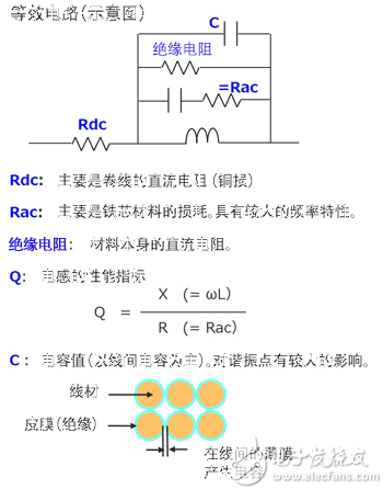
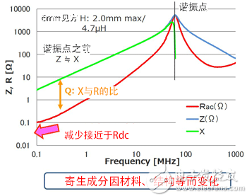
When it comes to choosing the most suitable capacitor and inductor for a switching power supply, I've already shared quite a bit about capacitors. Now, let's shift our focus to inductors. In my opinion, inductors are essential components in building a switching power supply. However, magnetic components like inductors can be quite challenging to understand. It's not uncommon for engineers to find them confusing. Despite this, switching power supplies are now a standard part of many designs and can't be avoided. To deepen our understanding of inductors, I'll go through some key points and answer common questions. So, where should we start when selecting an inductor? So, do you need to carefully check the specifications? Absolutely. Relying solely on the values provided can sometimes lead to serious issues. Let’s take a look at an excerpt from our product catalog below: The nominal inductance is obviously a mandatory parameter, measured at 100 kHz with a tolerance of ±30%. The self-resonant frequency (SRF) is the upper limit at which the inductor operates effectively. The minimum SRF is guaranteed, meaning the inductor will function normally below that frequency. DC resistance (Rdc) refers to the resistance of the winding, usually specified with a ±20% tolerance. The rated current is a critical parameter, and there are two main types: DC superimposed current and temperature rise current. The former refers to the maximum DC current before the inductance drops by 30%, while the latter is based on a 40°C temperature rise. Different manufacturers use different criteria, so it's important to verify these details. One thing to note is that not all manufacturers provide both types of rated current. If only one is available, it’s typically the lower of the two. Always confirm with the manufacturer for safety. Here’s a graph showing the relationship between DC superimposition, temperature rise, and the margins involved: This example illustrates the DC superimposed current rating. The idea is similar for temperature rise. The typ value is a representative average, while the guaranteed range provides a margin. Actual measurements may fall closer to the typ value or near the extremes. Comparing these values helps assess the performance and reliability of the inductor. But why do different manufacturers have varying conditions for the same feature? It often comes down to application requirements and design priorities. Some prioritize performance, others focus on cost or reliability. These factors influence how each manufacturer defines their ratings. What else should you consider when selecting an inductor? Understanding its equivalent circuit is key. Like capacitors, inductors have parasitic elements such as core losses (iron loss), copper loss (DC resistance), and stray capacitance. These affect performance, especially at high frequencies. In the equivalent circuit, Rdc represents the wire resistance, while Rac accounts for core losses. As frequency increases, the impedance changes, and the inductor behaves more like a capacitor after the resonance point. The Q factor, which measures efficiency, is calculated as the ratio of inductive reactance to resistance. A higher Q means less loss and better performance. Here’s a graph showing the frequency response of a 4.7 µH inductor. The red line represents iron loss, the blue line shows impedance, and the green line indicates inductive reactance. At high frequencies, the inductor starts to act more like a capacitor due to its internal capacitance. This is an important consideration when designing high-frequency circuits. Each inductor has unique characteristics based on its material and construction. Understanding these parasitic effects helps in making informed decisions during the design process. Whether you're working on a simple power supply or a complex system, careful selection of inductors ensures stable and efficient operation. Weatherproof/Waterproof Type F Outlets "Waterproof Type F Outlets Black,Waterproof Type F Outlets,Waterproof Outlet Plug,Waterproof Exterior Outlet " Yang Guang Auli Electronic Appliances Co., Ltd. , https://www.ygpowerstrips.com
First, it’s important to understand how to read inductor specifications. This might seem basic, but it’s crucial. Even if two inductors have the same nominal value, the conditions under which they are rated can vary significantly between manufacturers. For example, one manufacturer may specify both a maximum and minimum value, while another might only provide a typical value. This can lead to confusion if you don’t pay close attention.


