Communication between S7-1200 and G120 inverters based on USS communication protocol
Optical Time Domain Reflectometer OTDR Mini PRO OTDR,OTDR Fiber Optic Tester,handheld otdr,Handheld Smart OTDR Fiber Tester,Optical Light Source Shenzhen Runtop Technology Co.LTD , https://www.runtoptech.com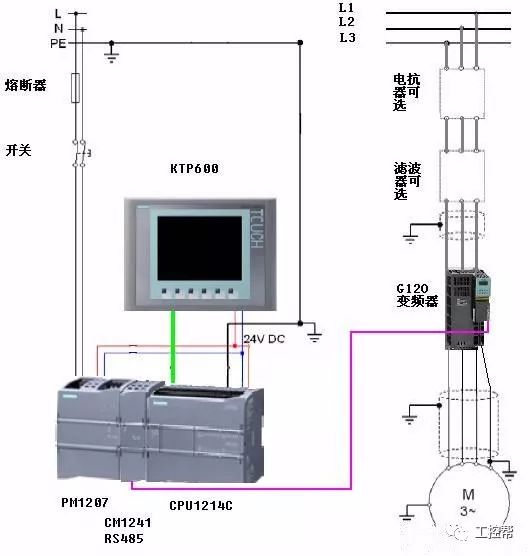 **Figure 1**: Control system principle and wiring diagram.
2. **Hardware Requirements**
The S7-1200 PLC has three CPU models: S7-1211C, S7-1212C, and S7-1214C. All of them can communicate with the G120 inverter via the CM1241 RS485 module using the USS protocol.
**PLC hardware used in this example includes:**
- PM1207 power supply (6EP1 332-1SH71)
- S7-1214C (6ES7 214-1BE30-0XB0)
- CM1241 RS485 (6ES7 241-1CH30-0XB0)
- Simulator (6ES7 274-1XH30-0XA0)
**G120 inverter hardware used in this example includes:**
- SINAMICS G120 PM240 (6SL3244-0BA20-1BA0)
- SINAMICS G120 CU240S (6SL3224-0BE13-7UA0)
- SIEMENS Motor (1LA7060-4AB10)
- Operator panel (XAU221-001469)
- USS communication cable (6XV1830-0EH10)
3. **Software Requirements**
The programming software used is Step7 Basic V10.5 (6ES7 822-0AA0-0YA0). We will now explain how to configure the USS communication between the S7-1214C and the G120 drives in Step7 Basic V10.5.
4. **Configuration Steps**
**4.1 PLC Hardware Configuration**
Start by creating a new project in Step7 Basic V10.5 as shown in Figure 2.
**Figure 1**: Control system principle and wiring diagram.
2. **Hardware Requirements**
The S7-1200 PLC has three CPU models: S7-1211C, S7-1212C, and S7-1214C. All of them can communicate with the G120 inverter via the CM1241 RS485 module using the USS protocol.
**PLC hardware used in this example includes:**
- PM1207 power supply (6EP1 332-1SH71)
- S7-1214C (6ES7 214-1BE30-0XB0)
- CM1241 RS485 (6ES7 241-1CH30-0XB0)
- Simulator (6ES7 274-1XH30-0XA0)
**G120 inverter hardware used in this example includes:**
- SINAMICS G120 PM240 (6SL3244-0BA20-1BA0)
- SINAMICS G120 CU240S (6SL3224-0BE13-7UA0)
- SIEMENS Motor (1LA7060-4AB10)
- Operator panel (XAU221-001469)
- USS communication cable (6XV1830-0EH10)
3. **Software Requirements**
The programming software used is Step7 Basic V10.5 (6ES7 822-0AA0-0YA0). We will now explain how to configure the USS communication between the S7-1214C and the G120 drives in Step7 Basic V10.5.
4. **Configuration Steps**
**4.1 PLC Hardware Configuration**
Start by creating a new project in Step7 Basic V10.5 as shown in Figure 2.
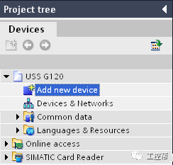 **Figure 2**: New S7 1200 project.
In the hardware configuration, add the S7-1214C CPU and the CM1241 RS485 module.
**Figure 2**: New S7 1200 project.
In the hardware configuration, add the S7-1214C CPU and the CM1241 RS485 module.
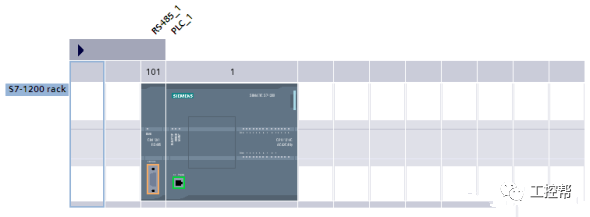 **Figure 3**: S7 1200 Hardware Configuration.
Set the IP address of the Ethernet interface and connect the PG to the PLC.
**Figure 3**: S7 1200 Hardware Configuration.
Set the IP address of the Ethernet interface and connect the PG to the PLC.
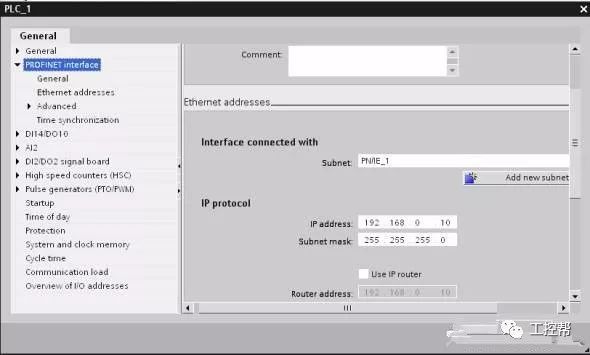 **Figure 4**: Settings for the S7 1200 IP Address.
**4.2 G120 Parameter Setting**
Below is a table of key parameters set on the G120 inverter:
| Serial No. | Feature | Parameter | Value |
|------------|----------------------------|-----------|-----------|
| 1 | Factory reset | P0010 | 30 |
| 2 | Factory reset | P970 | 1 |
| 3 | Quick start | P0010 | 1 |
| 4 | Motor rated voltage | P0304 | 380V |
| 5 | Motor rated power | P0307 | 5.5KW |
| 6 | Motor rated frequency | P0310 | 50Hz |
| 7 | Motor rated speed | P0311 | 1350r/min |
| 8 | USS command source | P0700 | 5 |
| 9 | Frequency setting source | P01000 | 5 |
| 10 | Min motor frequency | P1080 | 0.0Hz |
| 11 | Max motor frequency | P1081 | 50.0Hz |
| 12 | Start ramp time | P1120 | 10.0S |
| 13 | Delay ramp time | P1121 | 10.0S |
| 14 | End quick start | P3900 | 1 |
| 15 | Expert mode | P0003 | 3 |
| 16 | Reference frequency | P2000 | 50.0Hz |
| 17 | USS baud rate | P2010 | 9 |
| 18 | USS slave address | P2011 | 1 |
| 19 | USS PZD length | P2012 | 2 |
| 20 | USS PKW length | P2013 | 4 |
| 21 | Communication monitoring | P2014 | 0 |
| 22 | Save to E2PROM | P0971 | 1 |
| 23 | Expert mode | P0003 | 3 |
| 24 | Parameter mode | P0010 | 30 |
| 25 | Transfer parameters | P0802 | 1 |
**Table 1**: G120 inverter parameter settings.
*Note: Parameters 17–20 must be consistent between the PLC and the inverter. Otherwise, communication errors may occur.*
5. **USS Communication Principle and Programming Implementation**
**5.1 Basic Principles of S7-1200 and G120 Communication via USS**
The S7-1200 provides a dedicated USS library for communication, including function blocks such as **USS_DRV**, **USS_PORT**, **USS_RPM**, and **USS_WPM**. These are essential for controlling and reading data from the G120 inverter.
- **USS_DRV**: Main block for data exchange with the inverter.
- **USS_PORT**: Interface for the communication module.
- **USS_RPM**: Reads inverter parameters.
- **USS_WPM**: Writes parameters to the inverter.
Each S7-1200 CPU can support up to 3 communication modules, and each CM1241 RS485 supports up to 16 inverters. Thus, up to 48 inverters can be connected.
**5.2 Programming for USS Communication**
**1. Programming the USS_PORT Function Block**
The USS_PORT function block handles communication on the USS network. It is crucial for defining the communication module, baud rate, and data block. For example:
- **PORT**: Specifies the communication module.
- **BAUD**: Matches the inverter's P2010 setting.
- **USS_DB**: Data block for communication.
- **ERROR/STATUS**: Indicates communication status.
The communication interval depends on the baud rate. For example, at 57600 bps, the minimum interval is 36.1ms, and the timeout should be set accordingly.
**2. Programming the USS_DRV Function Block**
This block controls the inverter’s operation and reads its status. Key parameters include:
- **RUN**: Start command.
- **OFF2/OFF3**: Stop commands.
- **SPEED_SP**: Speed setpoint.
- **DRIVE**: Inverter station address.
- **PZD_LEN**: Process word length.
Note: The PKW length must be set to 4 for proper communication.
**3. Programming the USS_RPM Function Block**
Used to read inverter parameters. Ensure that data types match correctly, and avoid initial values of 0 to prevent errors.
**4. Programming the USS_WPM Function Block**
Used to write parameters to the inverter. Again, ensure correct data types and avoid zero initial values.
**5.3 Debugging Tips**
When multiple inverters are connected, ensure that each USS_DRV uses the correct station address. Avoid simultaneous read/write operations. If issues arise, adjust based on site conditions and network setup.
**Figure 4**: Settings for the S7 1200 IP Address.
**4.2 G120 Parameter Setting**
Below is a table of key parameters set on the G120 inverter:
| Serial No. | Feature | Parameter | Value |
|------------|----------------------------|-----------|-----------|
| 1 | Factory reset | P0010 | 30 |
| 2 | Factory reset | P970 | 1 |
| 3 | Quick start | P0010 | 1 |
| 4 | Motor rated voltage | P0304 | 380V |
| 5 | Motor rated power | P0307 | 5.5KW |
| 6 | Motor rated frequency | P0310 | 50Hz |
| 7 | Motor rated speed | P0311 | 1350r/min |
| 8 | USS command source | P0700 | 5 |
| 9 | Frequency setting source | P01000 | 5 |
| 10 | Min motor frequency | P1080 | 0.0Hz |
| 11 | Max motor frequency | P1081 | 50.0Hz |
| 12 | Start ramp time | P1120 | 10.0S |
| 13 | Delay ramp time | P1121 | 10.0S |
| 14 | End quick start | P3900 | 1 |
| 15 | Expert mode | P0003 | 3 |
| 16 | Reference frequency | P2000 | 50.0Hz |
| 17 | USS baud rate | P2010 | 9 |
| 18 | USS slave address | P2011 | 1 |
| 19 | USS PZD length | P2012 | 2 |
| 20 | USS PKW length | P2013 | 4 |
| 21 | Communication monitoring | P2014 | 0 |
| 22 | Save to E2PROM | P0971 | 1 |
| 23 | Expert mode | P0003 | 3 |
| 24 | Parameter mode | P0010 | 30 |
| 25 | Transfer parameters | P0802 | 1 |
**Table 1**: G120 inverter parameter settings.
*Note: Parameters 17–20 must be consistent between the PLC and the inverter. Otherwise, communication errors may occur.*
5. **USS Communication Principle and Programming Implementation**
**5.1 Basic Principles of S7-1200 and G120 Communication via USS**
The S7-1200 provides a dedicated USS library for communication, including function blocks such as **USS_DRV**, **USS_PORT**, **USS_RPM**, and **USS_WPM**. These are essential for controlling and reading data from the G120 inverter.
- **USS_DRV**: Main block for data exchange with the inverter.
- **USS_PORT**: Interface for the communication module.
- **USS_RPM**: Reads inverter parameters.
- **USS_WPM**: Writes parameters to the inverter.
Each S7-1200 CPU can support up to 3 communication modules, and each CM1241 RS485 supports up to 16 inverters. Thus, up to 48 inverters can be connected.
**5.2 Programming for USS Communication**
**1. Programming the USS_PORT Function Block**
The USS_PORT function block handles communication on the USS network. It is crucial for defining the communication module, baud rate, and data block. For example:
- **PORT**: Specifies the communication module.
- **BAUD**: Matches the inverter's P2010 setting.
- **USS_DB**: Data block for communication.
- **ERROR/STATUS**: Indicates communication status.
The communication interval depends on the baud rate. For example, at 57600 bps, the minimum interval is 36.1ms, and the timeout should be set accordingly.
**2. Programming the USS_DRV Function Block**
This block controls the inverter’s operation and reads its status. Key parameters include:
- **RUN**: Start command.
- **OFF2/OFF3**: Stop commands.
- **SPEED_SP**: Speed setpoint.
- **DRIVE**: Inverter station address.
- **PZD_LEN**: Process word length.
Note: The PKW length must be set to 4 for proper communication.
**3. Programming the USS_RPM Function Block**
Used to read inverter parameters. Ensure that data types match correctly, and avoid initial values of 0 to prevent errors.
**4. Programming the USS_WPM Function Block**
Used to write parameters to the inverter. Again, ensure correct data types and avoid zero initial values.
**5.3 Debugging Tips**
When multiple inverters are connected, ensure that each USS_DRV uses the correct station address. Avoid simultaneous read/write operations. If issues arise, adjust based on site conditions and network setup.