AC voltage regulator working principle - Database & Sql Blog Articles
I. Classification of Voltage Regulators According to different classification methods, voltage regulators can be divided into three main types: electronic induction oil regulators, dry contact voltage regulators (including direct and compensation regulators), and dry-type non-contact voltage regulators (often with a compensation function). Based on the power supply environment, they can also be categorized as single-phase AC voltage regulators or three-phase AC voltage regulators. Figure II Point A represents the input side of the single-phase voltage regulator, while point B is the output side. This type of regulator, known as a direct voltage regulator, operates based on the principle of an autotransformer. In the diagram, the AN side is the input of the autotransformer, and the BN side is the output. If the input voltage is higher than the set output of 220V, the autotransformer functions in a buck mode. If the input voltage is lower than 220V, it operates in a boost mode. The key difference from a standard autotransformer is that the input point A can slide between 0V and 250V, allowing for continuous adjustment of the input voltage to maintain a stable output. This sliding arm is typically driven by a motor through a gear system, and its movement is controlled by the voltage regulation circuit. The sampling circuit monitors the output voltage, and when it rises above the desired level, the motor moves in the direction of the buck mode until the target voltage is reached. Conversely, if the output voltage drops, the motor rotates in the boosting direction until the correct voltage is achieved. The capacity of such a regulator is fully supported by the autotransformer. However, due to manufacturing limitations, it cannot be made very large and is typically used in low-power applications. To increase the power capability, a compensation transformer is added to expand the regulator’s capacity. 2. Principle of Single-Phase Compensation Regulator (Figure 4) This schematic shows a single-phase AC voltage regulator with compensation, consisting of a regulating transformer T1 and a compensation transformer T2. The low-voltage winding of the compensation transformer is connected in series with the main circuit, allowing most of the output power to be delivered directly to the load through this winding. By using a thick wire for the secondary coil, the regulator's power can be significantly increased. The regulating transformer only needs to handle the difference between the input and output voltages, which allows for a larger input voltage variation range. The actual capacity of the regulator is determined by the size of the regulating transformer. For example, if the input voltage is 240V and the desired output is 220V, the equation would be UO = U1 - ΔU, where ΔU is 20V in the opposite direction. If the input voltage is 200V, then UO = U1 + ΔU, with ΔU being 20V in the same direction. The compensation voltage ΔU is transmitted through the iron core of the compensation transformer and superimposed on the input voltage vector, stabilizing the output at the required level. When the sliding arm is at point C, the voltage across CD is 220V, and the center point E divides the winding. When the sliding arm moves to point D, the high-voltage side of the compensation transformer experiences a change in the direction of the applied voltage. This adjustment allows the compensation voltage to vary in both magnitude and direction. Adjusting the compensation voltage involves moving the sliding arm. As it moves away from the center point E, the voltage between points F and G changes accordingly. When the input voltage is exactly 220V, the sliding arm at point E results in zero compensation voltage, meaning no addition or subtraction occurs on the low-voltage side of the compensation transformer, and the output matches the input. IV. Working Principle of Three-Phase Voltage Regulator A three-phase voltage regulator is essentially composed of three single-phase voltage regulators connected in a "Y" configuration. The control circuit and motor drive system work together to adjust the voltage regulating transformer, ensuring the output voltage remains stable. If all three sliding arms are driven by a single motor, it is called a three-phase voltage regulator. If each phase is adjusted independently by separate motors, the working principle is similar to that of a single-phase regulator. V. Ensuring Continuous Output During Regulation During the voltage regulation process, the carbon brush moves along the coil, changing the number of turns. This requires the carbon brush to always maintain contact with the coil to avoid power interruption. To ensure continuous output: 1. The carbon brush must have sufficient thickness to ensure that even before one coil is fully removed, another is already in contact. 2. At least two coils must overlap during the movement to maintain continuity. 3. There is always a turn-to-turn short circuit during operation. The thicker the carbon brush, the more coils are shorted, affecting the voltage. 4. The voltage across the short circuit is usually kept below 1V. High-power regulators often operate at 0.8–0.9V, while smaller ones may have 0.4–0.7V. If the voltage is too high, stability decreases, and the regulator may burn out.
Car cable harness, also known as a wire harness, cable assembly, wiring assembly or wiring loom, is an assembly of electrical cables or wires which transmit signals or electrical power. The cables are bound together by connector, terminal, cable ties, sleeves, electrical tape, conduit, PVC tube, corrugate tube, string, or a combination thereof.
Commonly used in automobiles, as well as construction machinery, cable harnesses provide several advantages over loose wires and cables. For example, many aircraft, automobiles and spacecraft contain many masses of wires which would stretch over several kilometres if fully extended. By binding the many wires and cables into a cable harness, the wires and cables can be better secured against the adverse effects of vibrations, abrasions, and moisture.
Car Wire Harness,Wiring Harness,Car Electrical Wiring Harness,American Autowire Mustang Harness Dongguan YAC Electric Co,. LTD. , https://www.yacentercn.com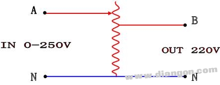
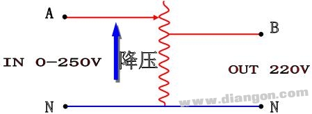 Figure II
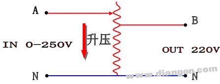 Figure 3
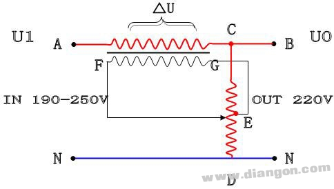 Figure 4
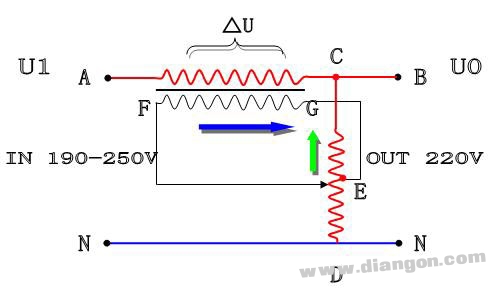 Figure 5
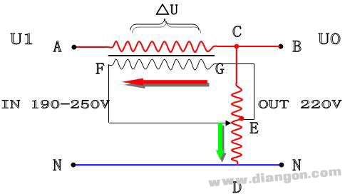 Figure 6
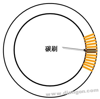 Figure 7