How to extend the operating temperature range of the FPGA
Some applications require electronic products to operate at temperatures above the maximum operating junction temperature specified by the device. The well camera design is a good example.
The life of any electronic device depends on its operating temperature. At higher temperatures, the device accelerates aging and its lifetime is reduced. However, some applications require electronics to operate at the maximum rated operating junction temperature of the device. Take the oil and gas industry as an example to illustrate this problem and the solution.
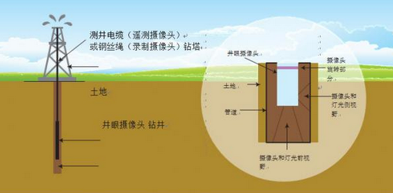
One client asked our Aphesa team to design a high-temperature camera that works in the well (as shown in Figure 1). The device requires a fairly large FPGA and requires a temperature of at least 125 ° C - the operating temperature of the system. As a consulting company that develops custom cameras and custom electronics including FPGA code and embedded software, we have extensive experience in high temperature working conditions. But for this project, we still spend a lot of energy.
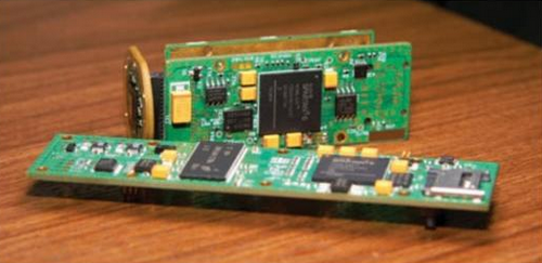
This product is a downhole two-color camera for oil well inspection (as shown in Figure 2). It performs embedded image processing, color reconstruction, and communication. The system features memory, LED drivers and high dynamic range (HDR) imaging. For this project, we chose to use the XA6SLX45 device from Xilinx (Spartan®-6 LX45 automotive device) because of its wide operating temperature range, robustness, small package size, large embedded memory and a large number of units.
The project is very challenging and has lots of fun. Here's how we did the project. Let's first review some of the concepts of temperature, including junction temperature, thermal resistance, and other phenomena. We will understand the reasons for the temperature rise in the device and list our solutions. We will also respond to possible hot issues and propose solutions.
In this particular project, the use of thermoelectric cooling is limited and we have to find other solutions.
temperature change
Electronic devices typically specify a maximum junction temperature. Unfortunately, system designers are concerned about the ambient temperature. The difference in ambient temperature and junction temperature will depend on the ability of the package to transfer heat and the ability of the cooling system to dissipate this heat out of the system chassis.
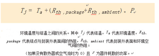
Thermal resistance is a thermal property and an indicator of the extent to which a given material blocks heat flow. Because of the thermal resistance, the temperature of the inside and outside of the component through which the heat flows through will be different, just as the presence of current causes the voltage across the resistor to be different. For a temperature difference of 20 °C inside and outside the fuselage, a device with a maximum junction temperature of 125 °C can operate up to 105 °C. The expression of the thermal resistance is °C/W, that is, the temperature difference between the inner side and the outer side when the heat is dissipated by 1W is the thermal resistance. Thermal resistance is a thermal property that measures the extent to which a given material blocks heat flow. This relationship is expressed as a graph in Figure 3.
The heat dissipated depends on the device, circuit, clock frequency, and code running on the device. The temperature difference between the internal (junction temperature) of the device and the environment (ambient temperature) is therefore dependent on the device, code, and operating schematic.
Common cooling solutions
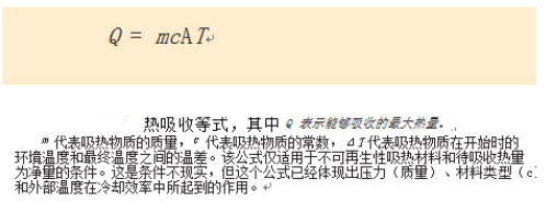
Where cooling is required in most designs, designers use passive cooling (heat sinks to increase the air contact surface to help dissipate heat into the air) or use active cooling. Active cooling solutions typically help to replace the cold air used to absorb heat from the device by forcing airflow. The ability of air to absorb heat depends on the temperature difference between the air and the device and the pressure of the air. Other solutions include liquid cooling, which replaces air with a liquid (typically water) for higher heat dissipation efficiency. The ability of air or fluid to absorb heat is determined by the heat absorption equation given in Figure 4. The final method often used by designers is thermoelectric cooling, which is to cool one side of the cooling plate by means of the PelTIer effect (by creating a voltage difference between the two electrodes connected to the semiconductor sample) while heating the other One side. Although this phenomenon helps to carry heat away from the device to be cooled, there is another major disadvantage in Peltier cooling: it requires a large amount of external power consumption.
In our case, airflow is not a solution because the amount of air in the chassis is limited and the air temperature quickly equalizes. Water cooling is also impossible because the distance between the water source and the tool is very long. So for us, the Peltier effect is the only cooling solution. Because the ambient temperature is fixed (we cannot heat a large amount of liquid like the formula in Figure 3), the thermoelectric effect cooler actually lowers the temperature of the electronic product. Unfortunately, because the cooling device requires a large current and the need to connect the surface to the tool with an extra long conductor, only a limited current is available for cooling and only a small temperature difference can be achieved.
In addition, since our device is a camera, the picture quality drops sharply with increasing temperature. So we have to optimize our cooling strategy to reduce the temperature of the image sensor as much as possible, rather than lowering the temperature of the FPGA, memory, LED driver or power circuit.
Since the Peltier effect can only be chosen to cool the image sensor, it is almost impossible to cool the FPGA, so our only option is to reduce the peak temperature inside the FPGA.
Hot cause
And rising temperatures have three sources of power consumption in digital devices: dynamic, static, and Joule effects. Dynamic power consumption is the power used to charge and discharge the trace capacitance when the gate is triggered. It is proportional to the clock rate and total capacitance. Static power is a function of device type, core voltage, and technology. This power consumption is due to the power consumption of the core or I/O.
When heat is generated at a certain point in space, it will pass to the periphery, causing the surrounding area to heat up. If the surrounding area is not a heat source, the heat will spread and the temperature rise will be limited. As long as you wait a long enough time, the temperature will eventually equalize throughout the device. If the surrounding area is made up of other heat sources, because each heat source will bring heat to another heat source, the temperature will increase net.
If many heat sources are concentrated on a small area, the temperature of this area will rise faster than elsewhere, resulting in hot spots.
Due to the limited junction temperature of the device, the hottest temperature should not exceed the maximum junction temperature. After knowing the power consumption of the device and the temperature of the package, we can estimate the average junction temperature.
The last heat source is related to the Joule effect produced by the current flowing in the conductor.
What happens if the maximum temperature is exceeded?
As the operating temperature increases, the life of the device will decrease and the components will age faster. Certain aging processes, such as electromigration and electro-erosion, only occur at higher temperatures. Electromigration occurs in the presence of moisture and electric fields. At this point the atoms of the conductor move in their ionic form from their initial position and reset in another place, leaving a gap. This gap reduces the effective width of the conductor at that location, causing the electric field at that location to increase, thereby inducing more electromigration. This chain reaction causes a crack (open circuit) at the location where the atom is removed or a short circuit (dendritic) where the atom is relocated. A small number of layers of water molecules are sufficient to initiate the ionization of the metal, triggering electromigration. This phenomenon is significantly more severe with increasing temperature.
Corrosion phenomena such as iron rust involve moisture and harmful gases. The semiconductor material is enclosed in its protective package. Such packages are generally highly absorbent to moisture, but the materials used in the fabrication do not readily produce corrosive ionic solutions. This corrosion can adversely affect leadframe and package wiring in most cases. The most important hazardous materials are the phosphorus contained in the silicon passivation layer and some of the contaminants left in the semiconductor fabrication process or packaging process. Exposure to human skin and other chemicals during transportation, welding, and assembly is another possible source of harmful atoms that cause contamination.
When heterogeneous materials are joined together, less expensive materials are prone to corrosion (electrochemical corrosion) relative to more expensive materials. This type of corrosion is another cause of reduced performance over time.
When the junction temperature is exceeded, the lifetime of the device cannot be guaranteed and may be greatly shortened. If the temperature continues to increase, the device may fail immediately.
The performance of the device also depends on the speed. The device will drop at higher temperatures, so their maximum clock rate will decrease.
The maximum temperature limit for Spartan-6 XA (automotive grade) FPGAs is 125 °C for the minimum lifetime requirements (reliability considerations) and guaranteed clock frequency capability (performance requirements). Other reasons include packet RAM cell leakage and bit errors due to such leakage.
Multiple solutions
To overcome the challenges of our oil well camera design, we have implemented a variety of solutions.
One of the most important decisions is to choose the right size device. The larger the static power consumption of the larger device, the better the heat dissipation of the device and the avoidance of hot spots. Devices certified for automotive use have a long service life even at high temperatures, making them a suitable solution for industrial applications where life is not critical. We have evaluated the code in the lamination problem during the temperature-free cycle of the LX25 and LX45 devices in the XA (vehicle) series and measured the total power consumption and temperature of the device housing. Sometimes it is acceptable to increase the average device temperature if the peak temperature is low. We also evaluated the service life in the accelerated aging test.
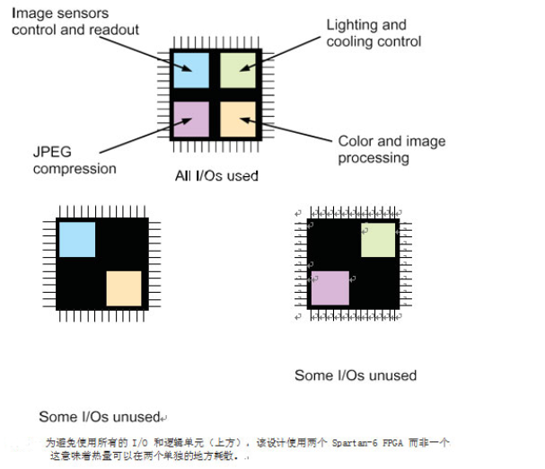
Our next design choice is to set limits for device usage. To reduce the amount of heat dissipated by the device, we avoid using logic cells and memory as much as possible. The unused portion of the device consumes static power but does not consume dynamic power.
We also applied clock gating. Because dynamic power is dependent on the clock rate, we can use clock gating to offset the dynamic power consumption of unused modules. If the clock tree is not triggered, the power consumption of that part of the device will decrease.
We can also keep the number of I/Os we use to a minimum. This also reduces the power consumption of the I/O modules.
Therefore, by using part of the I/O as a virtual ground, we shorten the transmission distance of the internal current of the device, thereby reducing the Joule effect of the power supply trace. Virtual ground also helps to transfer heat to the ground.
Since we don't want to use all the I/O and all the logic cells, we chose to distribute this design on both FPGAs (Figure 5). This allows heat to be dissipated in two separate locations.
We also use multiple ground planes. This technique helps to transfer heat from lower temperatures to lower temperatures and provides additional heat capacity. For the reliability of the development board, it should be considered when designing the thermal plane.
An important step is to optimize our code to
Reduce the clock rate. Lowering the clock rate reduces power consumption, but it also allows the device to operate at higher temperatures. As an example, we evaluated trade-offs between slow parallel design and fast pipelined design.
To improve design performance, we ensure that the individual components are dried and covered with a protective layer that resists moisture before final assembly. In addition, the device will age faster at high temperatures. Product certification can be used to measure the actual life of a designed device as a function of temperature.
We also use an aging process in production to pre-age the device and remove parts that are aging faster than other parts (early failure), leaving only the best parts.
Equally important to our design process is the use of a junction temperature that does not exceed 125 °C. In addition, we have worked hard to operate at 125 °C without thermoelectric cooling.
To recover or at least detect bit errors in memory cells or in communication. It can also be restored if the state machine ends in an unused state.
We found that using the Xilinx Power Estimator (XPE) in our design was a good start. The TVivado® Design Suite provides power estimation tools for designs that use newer devices. However, measuring power consumption on real devices and comparing different versions of the code proved to be the most ideal and accurate method.
Non-thermoelectric cooling
Combine the above techniques with Cyclic Redundancy Check (CRC) and other types of error detection and corrective actions. We used these techniques in various locations in the design, and we got a camera that could work at 125°C ambient temperature with SDRAM management, communication bus and image processing capabilities.
Portable Wireless Speaker,Mini Wireless Speaker,Custom Bluetooth Wireless Speaker,Waterproof bluetooth speaker,Wholesale bluetooth speakers
Shenzhen Konchang Electronic Technology Co.,Ltd , https://www.eclinusb.com