Research on AM402-based Current Output Capacitive Angle Sensor
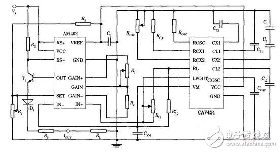
introduction The traditional differential capacitance angle sensor has a limited measurement angle, and the moving piece has a direct electrical connection with the outside world, and the electrodes are respectively led out from the moving piece and the static piece. The follower electrode of the driven piece usually adopts the method of bearing, clip or metal wire. During the rotation of the moving piece, not only the friction between the rotating shafts is present, but also the contact between the lead wire and the rotating shaft of the rotor is poor, and mechanical failure occurs. Interference and errors affect measurement accuracy. Therefore, a new type of capacitive angle sensor has been designed to improve the structure and overcome the defects in the traditional differential capacitance angle sensor structure design. 1, structural design The sensor system uses a new structural design approach. The moving piece is composed of two opposite sector-shaped metal plates with an opening angle of 90°, and the middle portion of the metal plate is connected; and the static piece is composed of two fan-shaped metal plates with an opening angle of 90° and a middle portion, and the electrodes are respectively from two. The static film is taken out as the signal output of the sensor. In essence, this new structure of the capacitive angle sensor is equivalent to the series connection of two variable capacitors, and the series value of the capacitor varies according to the change of the relative angle between the metal plate of the moving piece and the fixed metal plate. The design of the lead electrode from the static piece is convenient, which facilitates the change of the angle of the movable piece relative to the static piece, and the moving piece has no electrical connection with the outside world, thereby avoiding friction and mechanical failure caused by rotation during the measurement process, thereby realizing no Contact measurement improves measurement accuracy. 2, the basic principle The basic principle of a capacitive sensor is based on the relationship between the capacitance between the objects and the structural parameters. For a plate capacitor, if the parallel plate is infinite, ignoring its edge effect, its capacitance formula is expressed as: It can be seen from the formula (1) that the changes in the dielectric constant, the relative area of ​​the plates, or the distance between the plates can be reflected as changes in the capacitance value. Therefore, this principle can be used to measure the displacement of an object, the state parameters of a substance, and the like. According to the design structure, the radius of the static angle of the capacitive angle sensor is R, the distance between the rotating piece and the static piece (ie the distance between the plates) is d, the dielectric constant of the air is En, and each piece is rotated during the rotation. The change in the relative area between the rotating piece and the static piece with an angle of 90~ is Δs. In the initial state, the relative area of ​​the rotating piece and the static piece is zero, then ΔS1=ΔS2=Δs. because: The total capacitance change is: Let the rotating piece start from the initial position, and the angle that the rotating piece rotates is the mouth. The amount of capacitance change periodically changes with angle, and is printed at 0 to 3. Within each quadrant, the amount of change in capacitance is linear with the amount of change in angle 0. The maximum amount of change is: 3. Capacitance signal measurement and its conversion circuit 3.1 Capacitor-voltage conversion circuit CAV424 CAV424 is a versatile integrated circuit that handles the conversion of various capacitive sensor signals and converts capacitive signals into voltage signals. It also has the functions of signal acquisition (relative to capacitance change), processing and differential voltage output. It can measure the difference between the measured capacitance and the reference capacitance, ie 5%~100 relative to the reference capacitance value (10PF~2nF). The capacitance value in the range of % is converted and converted into a corresponding differential voltage output with high detection sensitivity. It also integrates a built-in temperature sensor, which can be used directly to monitor temperature when digital signal correction is required. Using CAV424 as a conditioning circuit for capacitive sensors, it can overcome the effects of parasitic capacitance and environmental changes, improving measurement accuracy and anti-interference ability. At the same time, the sensor has fewer external components, the processing circuit is relatively simple, and the instrument is small in size. 3.2 voltage-current conversion circuit AM402 The AM402 is an integrated circuit that processes differential signal input and current output interfaces. It can convert the input weak sensor differential voltage signal into a two-wire output (4 to 20 mA) or three-wire output (0/4 to 20 mA) in line with industry standards. Current signal. The AM402 consists of three basic units: (1) High precision preamplifier. It has a large gain adjustment range and is suitable for different signal input ranges. It can be used for sensor signal processing in a variety of different ranges. (2) Current output stage controlled by voltage. The output current can be adjusted over a wide range by adjusting the bias voltage. (3) Adjustable reference voltage. It can supply 5V or 10V to the sensor or external components. The actual measuring circuit of the capacitive angle sensor, wherein the series portion of the variable capacitors C1 and C2 is the equivalent circuit portion of the capacitive sensor. 4. Experiment and analysis In the experimental design, according to the range of the output current of the AM402 three-wire system, the external component of the capacitive sensor signal conversion integrated circuit chip CAV424 is adjusted, so that the output differential voltage value is 0-200 mV, that is, input to the voltage-current conversion interface circuit AM402. The voltage value is 0 ~ 200mV, and the AM402 uses a three-wire output mode, the output current range is 4 ~ 20mA. According to the above theoretical derivation, in practical applications, the angle sensor is only suitable for taking the linear change region where the current output increases with the increase of the angle in the range of 0 to 2/π, so in the measurement process, only 0- is measured. The output of the current in 2 / π varies with angle. The measurement of the change in angle through the two current outputs of the load. According to the most-'b~-multiplication principle, the experimental data is curve-fitted to obtain the first-order optimal linear fitting curve. The results show that the actual measured values ​​are basically consistent with the theoretical values, and are very close to the fitted curve; Iout is linearly output in the range of 0 to 90~ measured angles. 5, discussion It can be seen from the experimental results that the initial current value of the output curve is slightly less than 4 mA compared with the actual measured value. This is because during the experiment, the integrated circuit AM402 is adjusted according to the actual output current value, so that the initial state bias current is 4 mA. During the adjustment process, the sensor itself is subject to the parasitic capacitance existing in the surrounding environment. And the influence of the human body on the sensor during the adjustment process, and thus the measurement result of the initial value causes an error. Moreover, the circuit CAV424, in which the capacitance sensor signal is converted into a voltage, also has certain environmental interference and error, and the output differential voltage is amplified by the preamplifier portion inside the AM402, which affects the output current value. 6, the conclusion The new capacitive angle sensor is simple in structure and can measure angular changes of 090~. With CAV424 and AM402, the change signal of the capacitor can be converted into a current output of 4 to 20 mA standard. The experiment obtained the ideal linear output DC current signal, which can be widely used in practical angle measurement and automatic control. By adopting shielding measures on the sensor itself and its external components, the interference of external interference to the system can be effectively reduced, thereby reducing the measurement error. Led Ceiling Lamp,Modern Ceiling Lamps,Led Recessed Ceiling Lights,Remote Control Ceiling Lights Changxing Fanya Lighting Co.,Ltd , https://www.fyledlights.com