Design scheme of a set of heat meter temperature control system
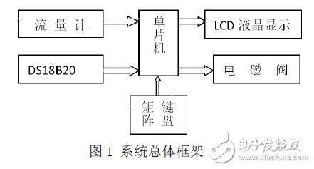
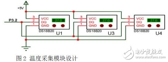
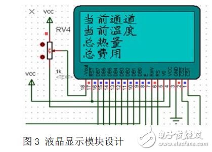
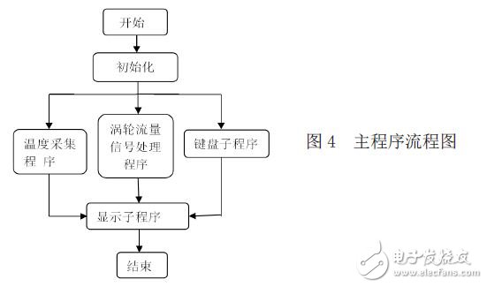
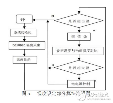
0 Preface With the improvement of living standards, people have put forward higher requirements for the living environment. Good temperature control plays a very important role in improving people's quality of life. Especially in the north, urban residents generally adopt central heating in winter, and the quality of heating is directly related to people's production and life. At present, the vast majority of district heating in China lacks a powerful monitoring system, unable to complete on-demand heating and achieve effective control of temperature data, thus causing a waste of heating heat. With the gradual enhancement of people's awareness of energy conservation, there is an urgent need for a smart heat meter temperature control system that is simple to operate, energy-saving, environmentally-friendly and efficient. 1 overall system design According to the relationship between heat and flow, temperature: Q=CM(T1-T0) where Q is the heat dissipation of the heat sink (unit: J); C is the specific heat of water 4.2*103J/kg° C; T1-T0 is the temperature difference between the inlet and outlet of the radiator (° C); M is the flow rate (L) of water flowing through the radiator, that is, the mass (kg). According to the above formula, as long as the flow rate and temperature difference can be measured, the heat dissipation amount of the radiator can be calculated. The signal detected by the temperature sensor is transmitted to the single-chip microcomputer, and the flow information is transmitted to the single-chip microcomputer, and the temperature setting is completed by using the matrix keyboard. After the MCU has processed the data, it sends a command to the LCD and controls the solenoid valve. The overall framework of the system is shown in Figure 1. 2 module introduction The design mainly consists of a single chip, a liquid crystal display, a digital temperature sensor, a liquid flow meter, a keyboard, a solenoid valve and the like. Temperature display: The MCU controls the digital temperature sensor (DS18B20), and the temperature signal is transmitted from the digital temperature sensor to the MCU through a single bus. After the MCU data processing, the current temperature information is sent to the LCD (LCD12864) for display. Heat display: The flow information (pulse signal) detected by the flowmeter is transmitted to the MCU. After the MCU data processing, the current heat information is sent to the LCD (LCD12864) for display. Temperature setting: The system can also set the temperature limit value by pressing the button. The MCU compares the temperature of the digital temperature sensor with the set temperature value and issues a command to control the action of the relay. 2.1 Introduction to DS18B20 The DS18B20's digital thermometer provides 9 to 12 digit Celsius measurements with alarm and non-volatile user programmable upper and lower trigger points. The DS18B20 communicates over the 1-Wire bus and requires the definition of only one data line (and ground) to communicate with the central microprocessor. The DS18B20 is a temperature sensor for the "one-wire bus" interface. It uses the patented on-board technology. Its sensor components and conversion circuits are integrated in an integrated circuit shaped like a triode. Because the first-line bus is unique, a microprocessor can control the DS18B20 with a large area. 2.2 AT89S52 MCU The single-chip microcomputer (Single-chip Microcomputer or MicrocontrollerUnit) concentrates the CPU, ROM, RAM, I/O interface circuit and internal system bus on a large-scale integrated circuit chip to form a single-chip microcomputer. The AT89S52 is a low power, high performance CMOS 8-bit microcontroller with 8K in-system programmable Flash memory. Manufactured using Atmel's high-density volatile memory technology, it is fully compatible with industrial 80C51 product instructions and pin functions. The program memory can program the system on-chip Flash and is also suitable for regular programmers. The single-chip, flexible 8-bit CPU and system-programmable Flash make the AT89S52 a very flexible and efficient solution for many embedded control systems. 3 main module circuit design 3.1 Temperature signal acquisition circuit design This system is a multi-point temperature test. The DS18B20 uses an external power supply. In theory, 256 DS18B20s can be hung on a single data bus. However, in practice, it is found that if more than 25 DS18B20s are connected, power consumption may still occur. In addition, the single bus length should not exceed 80M, otherwise it will affect the data transmission. In practical applications, a MOSFET can also be used to connect the I/O line directly to the power supply for pull-up, as shown in Figure 2. During the entire operation of the DS18B20, there are three key processes: searching for the DS18B20 serial number subroutine; starting the online DS18B20 as a temperature conversion subroutine: reading the temperature value subroutine of the online DS18B20. 3.2 LCD display circuit design The LCD12864 has a display resolution of 128&TImes;64, 8192 16*16 dot Chinese characters and 128 16*8 dot ASCII character sets, and has 4/8-bit parallel, 2-wire or 3-wire serial interfaces. the way. The flexible interface mode of the module and simple and convenient operation instructions can form a full Chinese human-computer interaction graphical interface. In addition, low voltage and low power consumption is another remarkable feature. The liquid crystal display scheme composed of the module is much more compact than the same type of graphic dot matrix liquid crystal display module, regardless of the hardware circuit structure or the display program, and the The price of the module is also slightly lower than the graphic LCD module of the same dot matrix. The design is shown in Figure 3. 4 system software design The function of the main program is: After the power is turned on, the system initialization operation is performed, mainly to initialize the timer/counter. The temperature acquisition program converts the temperature signal into a digital signal, which is input into the RAM memory of the microcontroller; converted into a BCD code converted into a hexadecimal equivalent of the scale conversion for temperature, and stored in the display buffer to display the subroutine. When used, it is responsible for sending the temperature of each buffer in the buffer to the LCD for display. The function of the flow signal processing program is to complete the measurement of the frequency and convert it into flow information by setting a timer, a timer, and an external interrupt. The main program flow chart is shown in Figure 4. The keyboard subroutine can complete the temperature setting by writing the button program. Figure 5 shows the algorithm flow of the temperature setting part. 5 Summary The system designed in this scheme improves various technologies and methods, and uses STC89C52 single-chip microcomputer as the control core to realize the control and operation of the whole system. The liquid flow meter adopts the turbine sensor to realize the collection of the liquid flow. The digital temperature sensor adopts the DS18B20 to realize the temperature signal acquisition, and the digital temperature signal is transmitted to the single-chip microcomputer, and the temperature setting can be completed through the matrix keyboard. The fixed temperature and the actual temperature issue a command to control the relay to open or close, and control the flow of the liquid to achieve the purpose of controlling the room temperature. This confirms the practicality of the scheme.
A Heated towel rack is not just something that keeps your towels from being crumpled on the floor - Towel Heater offer many benefits to your bathroom! STYLISH & FUNCTIONAL MAKE YOUR TOWEL RACK WORK FOR YOU. WARMER TOWELS RIGHT OUT OF THE SHOWER. DRY TOWELS DRY TOWELS QUICKLY AND EFFICIENTLY. HEATED TOWEL RACK COLLECTIONS.
Heated towel rails, once considered a luxury item are now commonplace in bathroom , elevating your bathroom, creating a functional yet creative centrepiece. A bathroom radiator is a great way to complete the look of any bathroom but also has the practical use of warming your towels.
Towel Bathroom Heater, Bathroom Fan Heater
Welcome to OEM
thanks
Towel Heater Electric Heated Towel Rail,Heated Towel Rail Bunnings,Freestanding Heated Towel Rail,Electric Towel Heater Fenry manufacturing Co., Ltd , https://www.cnfenry.com