Coupling and decoupling and dry goods analysis of pull-up and pull-down resistors
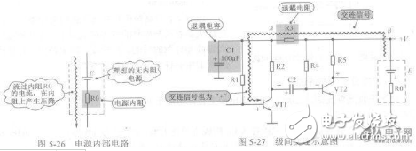
Coupling and decoupling What is a coupling capacitor? What is a decoupling circuit? The coupling refers to the process of transmitting signals from the first stage to the second stage, and generally refers to AC coupling when not indicated. Decoupling refers to the further filtering of the power supply to remove the interference of signals between the two stages through the power supply. The coupling constant is the time constant corresponding to the product of the coupling capacitance value and the second-stage input impedance value. Decoupling has three purposes: 1. Remove the high-frequency ripple in the power supply, and cut off the high-frequency signal of the multi-stage amplifier through the crosstalk of the power supply. 2. When the large signal is working, the circuit needs to increase the power supply, causing the power supply to fluctuate, and the effect of the power supply fluctuation on the input stage/high voltage gain stage when the large signal is reduced by decoupling; 3. Form a floating or floating power supply, complete the grounding of some parts of the ground or the power supply in a complex system. The high-frequency switching noise generated by the active device during switching will propagate along the power line. The main function of the decoupling capacitor is to provide a local DC power supply to the active device to reduce the propagation of switching noise on the board and direct the noise to ground. Excerpted from Lund's "Board-Level Electromagnetic Compatibility Design" article, the paper speaks well about the use of noise coupling paths, decoupling capacitors, and bypass capacitors. Please see. Interference coupling The interference signal generated by the interference source acts on the electromagnetic interference of the electronic control system through a certain coupling channel. The coupling method of interference is only through the wires, space, public lines, etc. acting on the electronic control system. The analysis mainly includes the following. Direct coupling: This is the most direct way to interfere with intrusion and is the most common way in the system. If the interference signal directly invades the system through the wire, it will cause interference to the system. For this coupling method, the filter decoupling method can be used to effectively suppress the incoming of the electromagnetic interference signal. Common impedance coupling: This is also a common coupling method. It is often the case that the currents of the two circuits have a common path. The common impedance coupling has two types: common ground and power supply impedance. Preventing this coupling should cause the coupling impedance to approach zero, leaving no common impedance between the interferer and the interfered object. Capacitive coupling: Also known as electric field coupling or electrostatic coupling, is a coupling method due to the presence of distributed capacitance. Electromagnetic induction coupling: also known as magnetic field coupling. It is a coupling method of electromagnetic field induction in internal or external space. A common method to prevent such coupling is to shield devices or circuits that are susceptible to interference. Radiation coupling: The electromagnetic field radiation also causes interference coupling, which is an irregular interference. This interference is easily transmitted to the system through the power line. In addition, when the signal transmission line is long, they can radiate interference waves and receive interference waves, which are called large line effects. Leakage coupling: The so-called leakage coupling is resistive coupling. This interference often occurs when insulation is reduced. I remember my previous point of view: the capacitance of the tantalum capacitor is generally larger, that is, the meaning of avoiding the coupling of noise to other parts; the bypass capacitor has a small capacity and provides a low-impedance noise return path. In fact, this statement can be considered as no big mistake. However, after consulting the relevant information, it was found that decouple and bypass have no difference at all, and the two can be interchanged in terms. The role of the two is vulgar: when the power is used. The so-called noise is actually the fluctuation of the power supply. The fluctuation of the power supply comes from two aspects: the fluctuation of the power supply itself, the voltage fluctuation caused by the difference between the load demand and the corresponding power supply system. The decoupling and bypass capacitors are all related to the noise caused by load changes. So there is no need for them to distinguish between the two. In fact, the magnitude and quantity of the capacitance value are also theoretically arguable. If you choose at random, you may encounter self-oscillation of the tantalum capacitor (bypass) and distributed parameters in some cases. So the true sense of detour and bypass is based on the actual situation of the load and power supply system. There is no need to make a distinction, and there is no essential difference. Capacitance is a must-have component in board design, and its quality has become a very important aspect of our judgment of board quality. 1 Capacitor function and representation. It consists of two metal poles with an insulating medium sandwiched between them. The characteristics of the capacitor are mainly DC-blocked AC, so it is mostly used for interstage coupling, filtering, decoupling, bypassing and signal tuning. The capacitor is represented by a "C" plus a number in the circuit, such as C8, which represents a capacitor numbered 8 in the circuit. 2 classification of capacitors. Capacitors are classified according to different media: gas dielectric capacitors, liquid dielectric capacitors, inorganic solid dielectric capacitors, and organic solid dielectric capacitor electrolytic capacitors. Divided by polarity: there are polar capacitors and non-polar capacitors. According to the structure can be divided into: fixed capacitor, variable capacitor, trimmer capacitor. 3 capacitor capacity. Capacitance capacity indicates the amount of energy that can be stored. The blocking effect of the capacitor on the AC signal is called capacitive reactance. The capacitive reactance is related to the frequency and capacitance of the AC signal. The capacitive reactance XC=1/2πf c (f indicates the frequency of the AC signal and C indicates the capacitance). 4 Capacitor capacity unit and withstand voltage. The basic unit of capacitance is F (method), and other units are: millifarad (mF), microfarad (uF), nanofarad (nF), and picofarad (pF). Since the capacity of the unit F is too large, we usually see units of μF, nF, and pF. Conversion relationship: 1F=1000000μF, 1μF=1000nF=1000000pF. Each capacitor has its withstand voltage value, expressed in V. Generally, the nominal withstand voltage of the electrodeless capacitor is relatively high: 63V, 100V, 160V, 250V, 400V, 600V, 1000V, etc. The withstand voltage of the pole capacitor is relatively low, and the general nominal withstand voltage values ​​are: 4V, 6.3V, 10V, 16V, 25V, 35V, 50V, 63V, 80V, 100V, 220V, 400V, and the like. 5 capacitor marking method and capacity error. Capacitor marking methods are divided into: direct labeling method, color labeling method and number labeling method. For larger capacitors, the direct standard method is often used. If it is 0.005, it means 0.005uF=5nF. If it is 5n, it means 5nF. Number standard method: Generally, three digits are used to indicate the capacity. The first two digits represent the effective digits, and the third digit is the number of tenths. For example, 102 means 10x10x10 PF=1000PF, and 203 means 20x10x10x10 PF. The color scale method, in the direction of the capacitor lead, uses different colors to indicate different numbers. The first and second rings represent the capacitance, and the third color represents the number of zeros after the significant digit (in pF). The values ​​represented by the color are: black=0, brown=1, red=2, orange=3, yellow=4, green=5, blue=6, purple=7, gray=8, white=9. The capacitance capacity error is represented by the symbols F, G, J, K, L, and M, and the allowable errors are respectively ±1%, ±2%, ±5%, ±10%, ±15%, ±20%. The positive and negative poles of the 6 capacitors are distinguished and measured. The black block with the mark on the capacitor is the negative pole. There are two semicircles on the position of the capacitor on the PCB, and the pin corresponding to the semicircle of the color is the negative pole. Also use the length of the pin to distinguish the positive and negative long legs from positive and the short legs to negative. When we don't know the positive and negative poles of the capacitor, we can use a multimeter to measure. The medium between the two poles of the capacitor is not an absolute insulator. Its resistance is not infinite, but a finite value, generally above 1000 megaohms. The resistance between the two poles of the capacitor is called an insulation resistance or a leakage resistance. Only when the positive electrode of the electrolytic capacitor is connected to the power supply (the black test pen when the power is blocked), and the negative terminal is connected to the negative power supply (the red test pen when the power is blocked), the leakage current of the electrolytic capacitor is small (the leakage resistance is large). On the contrary, the leakage current of the electrolytic capacitor increases (the leakage resistance decreases). In this way, we first assume that a very "+" pole, the multimeter uses R*100 or R*1K block, then the hypothetical "+" pole is connected with the black test pen of the multimeter, and the other electrode is connected with the red test pen of the multimeter. Record the scale of the needle stop (the needle has a large left value), and the digital multimeter can read the reading directly. Then discharge the capacitor (two leads touch), then the two test leads are reversed and the measurement is repeated. In the two measurements, the last position of the hand is left (or the resistance is large), and the black pen is connected to the positive electrode of the electrolytic capacitor. 7 experience in the use of capacitors and four misunderstandings. Some experience: When the polarity of the line cannot be determined in the circuit, it is recommended to use an electrodeless electrolytic capacitor. The ripple current through the electrolytic capacitor cannot exceed its allowable range. If the specified value is exceeded, a capacitor with a large ripple current is required. The operating voltage of the capacitor must not exceed its rated voltage. When soldering the capacitor, the soldering iron should be kept at a certain distance from the plastic housing of the capacitor to prevent the plastic sleeve from rupturing due to overheating. And the welding time should not exceed 10 seconds, the welding temperature should not exceed 260 degrees Celsius. Four misunderstandings: ◠The larger the capacitance, the better. Many people often prefer to use large-capacity capacitors in the replacement of capacitors. We know that the larger the capacitance, the stronger the current compensation capability provided to the IC. Not to mention that the increase in capacitance increases the volume, which increases the cost and also affects air flow and heat dissipation. The key is that there is parasitic inductance on the capacitor, and the capacitor discharge loop will resonate at a certain frequency. At the resonance point, the impedance of the capacitor is small. Therefore, the impedance of the discharge circuit is the smallest, and the effect of replenishing energy is also the best. However, when the frequency exceeds the resonance point, the impedance of the discharge loop begins to increase, and the capacity of the capacitor to supply current begins to decrease. The larger the capacitance of the capacitor, the lower the resonant frequency, and the smaller the frequency range in which the capacitor can effectively compensate the current. From the perspective of ensuring the ability of the capacitor to supply high-frequency current, the larger the better the capacitor is, the more accurate it is. There is a reference value in the general circuit design. ◠Capacitors of the same capacity, the more small capacitors are connected in parallel, the withstand voltage value, temperature resistance value, capacitance value, ESR (equivalent resistance), etc. are several important parameters of the capacitor. The lower the ESR, the better. ESR is related to the capacity, frequency, voltage, and temperature of the capacitor. When the voltage is fixed, the larger the capacity, the lower the ESR. In the card meter, multiple small capacitors are used and the connection space is limited. Therefore, some people think that the more parallel small resistors, the lower the ESR and the better the effect. In theory, this is to take into account the impedance of the capacitor pin solder joints. The use of multiple small capacitors in parallel does not necessarily highlight the effect. ◠The lower the ESR, the better the effect. Combined with our improved power supply circuit above, the input capacitor has a larger capacity for the input capacitor. Relative to the capacity requirements, the requirements for ESR can be appropriately reduced. Because the input capacitor is mainly withstand voltage, followed by the switching pulse of the MOSFET. For output capacitors, the withstand voltage requirements and capacity can be appropriately reduced. The requirements for ESR are higher, because there is enough current throughput to be guaranteed. However, it should be noted here that the ESR is not as low as possible, and the low ESR capacitor will cause the switching circuit to oscillate. The complexity of the vibration absorbing circuit also leads to an increase in cost. In the design of the board, there is generally a reference value here. This is used as a component selection parameter to avoid the increase of the cost caused by the vibration damping circuit. ◠Good capacitance represents high quality. "Only Capacitance Theory" was once a spurt, and some manufacturers and the media also deliberately made this thing a selling point. In board design, the level of circuit design is key. Some manufacturers can use two-phase power supply to make products that are more stable than those of four-phase power supply. Some high-priced capacitors do not necessarily make good products. To measure a product, we must consider all aspects and angles, and we must not exaggerate the effect of the capacitor intentionally or unintentionally. Pull up and pull down Pull-up resistor: 1. When the TTL circuit drives the COMS circuit, if the high level of the TTL circuit output is lower than the lowest level of the COMS circuit (generally 3.5V), then the pull-up resistor needs to be connected at the output end of the TTL to improve Output a high value. 2. The OC gate circuit must be connected with a pull-up resistor before it can be used. 3, in order to increase the drive capability of the output pin, some of the microcontroller pins often use pull-up resistors. 4. On the COMS chip, in order to prevent damage caused by static electricity, the unused pins cannot be suspended. Generally, the pull-up resistor is connected to reduce the input impedance and provide a discharge path. 5. The pin of the chip is added with a pull-up resistor to increase the output level, thereby improving the noise margin of the input signal of the chip and enhancing the anti-interference ability. 6. Improve the anti-electromagnetic interference capability of the bus. When the pins are suspended, it is easier to accept external electromagnetic interference. 7. The resistance mismatch in long-line transmission is easy to cause reflected wave interference, and the pull-down resistor is resistance matching, which effectively suppresses reflected wave interference. The selection criteria for the value of the pull-up resistor include: 1. It should be large enough to save power and the current sinking capacity of the chip; the resistance is large and the current is small. 2. It should be small enough to ensure sufficient driving current; the resistance is small and the current is large. 3. For high-speed circuits, excessive pull-up resistors may flatten the edges. Considering The above three points are usually selected between 1k and 10k. Similar to the pull-down resistor The selection of the pull-up resistor and the pull-down resistor should be set in combination with the characteristics of the switching transistor and the input characteristics of the lower-level circuit. The following factors should be considered: 1. The balance between drive capability and power consumption. The above pull-up resistor is an example. Generally speaking, the smaller the pull-up resistor is, the stronger the driving capability is, but the greater the power consumption, the design should pay attention to the balance between the two. 2. The drive requirements of the lower level circuit. Similarly, for the above pull-up resistor, when the output is high, the switch is turned off, and the pull-up resistor should be properly selected to provide sufficient current to the lower-level circuit. 3. High and low settings. The threshold levels of the high and low levels of different circuits will be different, and the resistors should be properly set to ensure that the correct level can be output. Take the above pull-up resistor as an example. When the output is low, the switch is turned on, and the pull-up resistor and the on-resistance of the switch should be kept below the zero level threshold. 4. Frequency characteristics. For example, the above pull-up resistor, the capacitance between the pull-up resistor and the drain-source of the switch and the input capacitance between the lower-level circuits form an RC delay. The larger the resistance, the greater the delay. The pull-up resistor should be set to account for the needs of the circuit in this regard. The principle of setting the pull-down resistor is the same as the pull-up resistor. When the OC gate outputs a high level, it is a high-impedance state. The pull-up current is provided by a pull-up resistor. The input terminal is not more than 100uA per port, and the output current of the output port is about 500uA. The standard operating voltage is 5V. The high and low thresholds are 0.8V (below this value is low); 2V (high threshold). When the pull-up resistor is selected: 500uA x 8.4K= 4.2 When the output is greater than 8.4K, the output can be pulled down to 0.8V or less. This is the minimum resistance value, and it will not be pulled down. If the output current of the output port is large, the resistance value can be reduced, and it can be lower than 0.8V when the pull-down is performed. When the output is high, the leakage current of the tube is ignored. The two input ports need 200uA. 200uA x15K=3V, that is, the pull-up resistor has a voltage drop of 3V, and the output port can reach 2V. This resistance value is the maximum resistance value, and then it will not reach 2V. Choose 10K available. COMS door can refer to 74HC series The leakage current of the tube can not be neglected during design. The actual current of the IO port is different at different levels. The above is only the principle. In one sentence, it is summarized as follows: when the output is high, the input port should be fed, and the output should not be low. The output port is fed (otherwise the excess current is fed to the cascaded input port, which is unreliable above the low level threshold) Band BC 5000,Band Vape, Band BC 5000Puffs,Band BC 5000 Puff Nanning Nuoxin Technology Co., LTD , https://www.nx-vapes.com