Signal integrity testing and simulation
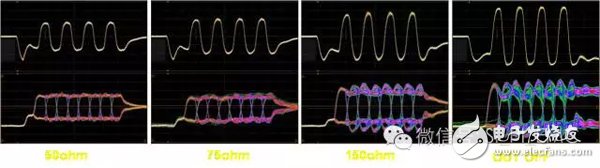
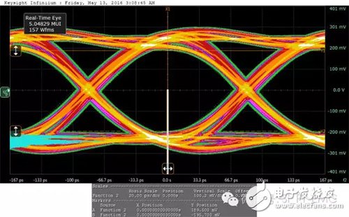
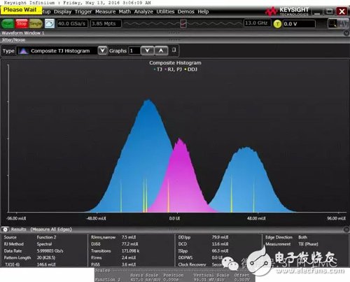
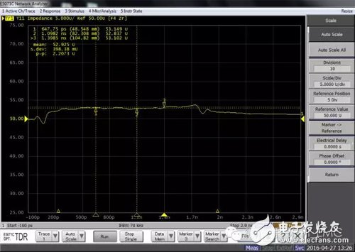
Signal integrity design is gaining more and more attention in product development, and signal integrity testing methods are numerous, frequency domain, and sometimes domain, and there are some comprehensive means, such as bit error testing. These methods are not suitable for use under any circumstances. They all have such limitations. If they are suitable, they can do more with less and avoid detours. This article introduces various test methods and explains how to use them in conjunction with actual hardware development activities. There are many test methods for signal integrity, and there are many instruments involved. Therefore, familiar with the characteristics of various test methods, and according to the characteristics and requirements of test objects, select appropriate test methods, hardware development for selection scheme, verification effect, problem solving, etc. Activities can greatly improve efficiency and play a multiplier role. Signal integrity test In the early days, there were not many ways to analyze signal integrity, but today, there are more and more means of signal integrity analysis, whether it is time domain or frequency domain, whether it is waveform or eye diagram, doubt is error. Rate and so on, as long as you want, in the near future, major manufacturers can design it. Although there are many testing methods now, these methods have both advantages and limitations. In fact, it is impossible to use them all. Some explanations are given below. Waveform test is the most commonly used method in signal integrity test. It is usually performed by oscilloscope. It mainly tests waveform amplitude, edge and glitch. By testing the parameters of the waveform, it can be seen whether the amplitude, edge time, etc. meet the interface level of the device. Request, is there any signal glitch? Since the oscilloscope is a very versatile instrument, it will be used by almost all hardware engineers, but it does not mean that everyone is using it well. Waveform testing also has to follow some requirements in order to get an accurate signal. The first is to require the bandwidth of the host and probe together to be sufficient. Basically, the test system (must pay attention to this is the system) the bandwidth is more than three times the test signal bandwidth. In actual use, some engineers just look for some probes to test, even K company's probe plugged into the T company's oscilloscope, this test is difficult to get accurate results. Second, pay attention to the details. For example, the test points are usually placed on the pins of the receiving device. If the conditions are not restricted, for example, the BGA packaged devices can be placed on the PCB traces or vias closest to the pins. It is too far away from the receiving device pin. Because the signal is reflected, the difference between the test result and the actual signal may be large. The ground wire of the probe should be selected as short as possible. Finally, you need to pay attention to the match. This is mainly for the case of testing with coaxial cable. The coaxial is directly connected to the oscilloscope. The load is usually 50 ohms and is DC-coupled. For some circuits, DC bias is required to directly connect the test system. Will affect the working state of the circuit, so that the normal waveform is not tested. Eye diagram testing is a common test method, especially for interfaces with specifications, such as USB, Ethernet, SATA, HDMI, and optical interfaces. Eye diagram testing of these standard interface signals, mainly using oscilloscopes with MASK (template), including general purpose oscilloscopes, sampling oscilloscopes or signal analyzers. These oscilloscopes have built-in clock extraction function to display eye diagrams. For oscilloscopes without MASK, You can use an external clock for triggering. When using the eye diagram test function, you need to pay attention to the number of test waveforms. Especially when judging whether the interface eye diagram meets the specifications, the number is too small, the waveform jitter is relatively small, and there may be some violations, such as a waveform entering a part of MASK. It may not be collected, and the misjudgment is passed. The number is too large, which will lead to the long test time and the efficiency is not high. Under normal circumstances, the number of test waveforms is not less than 2000, and it is suitable at around 3000. At present, there are some instruments that can use the analysis software to view the details of the violations in the eye diagram. For example, some sampling points are dropped in the MASK. In the past, it was not known which cases fell in because all the sampling points were accumulated. Going in, the overall effect looks like a long afterglow display. The new instrument takes advantage of its long storage and collects the waveform for processing and display. Therefore, every detail of the waveform can be retained, so it can view the violation of the waveform, such as the waveform is 000010 or 101010. It can help hardware engineers find the root cause of the problem. Jitter testing is gaining more and more attention now, as dedicated jitter testing instruments, such as the TIA (Time Interval Analyzer), SIA3000, are very expensive and use less. The most used is the oscilloscope plus software processing, such as Keysight's EZJIT, TEK's DPOJitter software. Through software processing, separate components such as RJ and DJ, and individual components in the DJ are separated. For this type of test, the selected oscilloscope, long memory and high speed sampling are necessary, such as memory above 2M, sampling rate of 20GSa/s. However, at present, the jitter test, the results of the solutions of various companies are quite different, and no one is an authority or industry standard. We specialize in cable assembly overmolding. Our customized molded cables are built precisly following customers' spec.Experienced proposal can be offered to customers for evaluation by considering stable quality and competitive price.
Custom cable overmoldings improve the quality, look and functionality of many electrical cables. From battery interconnects and molded plugs to custom molded plugs and many other custom designed assemblies – ETOP is a premier custom cable overmolding supplier to OEMs.
Molded Cables,Stranded Round Molded Cables,Molded Patch Cord Cable,4 Pole Waterproof Molded Cable,Waterproof Connectors ETOP WIREHARNESS LIMITED , https://www.oemwireharness.com