Comprehensive analysis of avionics standard ARINC653
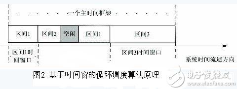
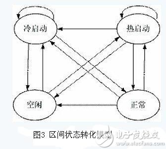
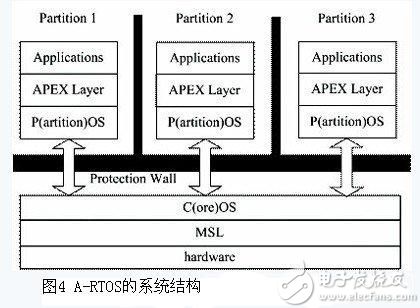
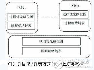
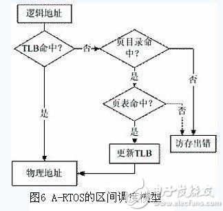
In traditional embedded real-time operating systems, both the kernel and the application run at the same privilege level, and the application has unlimited access to the entire system address space. Therefore, in some cases, the potentially dangerous actions of the application may affect the normal operation of other applications and the kernel, and even lead to system crash or misoperation. Major foreign embedded developers have introduced such an operating system that supports ARINC653 with kernel and application protection mechanisms. However, in the domestic embedded field, there is still a certain gap in such research. Based on this, this paper proposes a design idea of ​​avionics embedded real-time operating system (A-RTOS, Avionics RTOS), and implements it on the target board with MMU and advanced protection mode. Avionics standard ARINC653 ARINC653 focuses on the baseline operating environment for applications used by modular integrated avionics IMA (Integrated Modular Avionics). It defines the interface between the aeronautical application and the underlying operating environment and the mode of data exchange and the behavior of the service, and describes the runtime environment of the embedded avionics software. ARINC653 Supplement 1 supplements ARINC653 mainly includes the following points: In the system structure, the concept of System Partition is proposed. The application scheduling on the interval should be interval-level. These applications share interval resources. In terms of interval management, the interval scheduling is explained. The definition principle of the main time frame, and supplements the transition process of the interval mode; the principle of inter-interval communication is explained in more detail; the error level of health monitoring and the explanation of error handling are added. Software composition The core module software in avionics includes two categories: application software and core software. The APEX (APplication EXecutive) interface between the application software and the operating system OS defines a set of functions that the system provides for the application software. With this feature set, the application software can control the scheduling, communication and internal state information of the system. The APEX interface is equivalent to a high-level language for applications. For the OS, it is about the definition of parameters and entry mechanisms. Figure 1 shows the relationship between the various parts of ARINC653. Partition and interval management Partitioning is a core concept in ARINC653. In the IMA (Integrated Modular Avionics) system, a core module will contain one or more avionics applications, and these applications will be able to operate independently. Partitioning is a functional division in avionics applications. The unit of the partition is called the interval, and each execution unit in the interval is called a process. Each interval has its own independent data, context, and operating environment. This has the advantage of preventing errors in one interval from affecting other intervals. In addition, it makes the entire system easy to verify, validate and certify. Interval and interval management and scheduling are implemented by the OS. ARINC653 specifies a time window based cyclic scheduling algorithm for interval scheduling. The principle of this scheduling algorithm is shown in Figure 2. In order to complete the periodic scheduling of each interval, the OS maintains a fixed time length master time frame, which is periodically repeated during the running period of the module. Each time frame can be divided into several time windows. The system uses a predetermined configuration table to activate the operation of the corresponding interval within a specified time window. This ensures that each application accesses public resources during the time period allocated to it is not interrupted. ARINC supplement 1 complements the time definition principle of the main time frame. It stipulates that the size of the main time frame should be a positive integer multiple of the least common multiple of all interval periods in the core module, and should take into account the length of time and execution frequency of each execution of each interval. The system interval attribute and the start condition attribute were added when the ARINC653 Supplement 1 was released. The working modes of the interval include idle, cold start, hot start and normal, as shown in Figure 3. The required resources for each interval are specified at system build time, and interval objects are created when the interval initialization is complete. The OS starts the application interval when it enters the run mode, and then the interval enters the normal operation mode. The monitoring management function will restart the interval or stop interval in response to a fatal error. Design and implementation of A-RTOS system The system structure of A-RTOS is shown in Figure 4. In this system, each application works in the environment of its own interval, and the application and the kernel and each application are isolated by the protection wall and cannot be mutually damaged, thus ensuring the reliability of the core module. Isolation and protection mechanisms Isolation and protection are the primary characteristics of ARINC653 and one of the key points that must be addressed. A-RTOS mainly uses two ways to achieve isolation and protection between applications and the kernel and applications. The first way is to use the memory management unit MMU. The MMU can convert logical addresses to physical addresses and control access rights. This can protect the operating system kernel from intentional or unintentional destruction of the application software, and effectively prevent mutual destruction between the application software. Figure 5 shows the address translation process for the MMU's page directory/page table mode. The second way is the system call. In order to achieve protection between the kernel and the application, A-RTOS provides two modes of operation: user mode and system state. The operating system kernel is running in the system state. Therefore, the application of the user mode cannot directly call the function interface provided by the system kernel, and must be performed by the TRAP system call method. In this way, when the user mode application needs to call the system call provided by the kernel, first execute a special set of instructions to make the system enter the system state to execute the required system call. When the call is completed, the kernel will execute another group. The feature instruction returns the system to the user mode. Each system that supports protection mode provides a dedicated soft interrupt command to complete the function from user mode to system state. The system hooks up a soft interrupt handler. All system calls are entered through this soft interrupt and distinguished by different parameter values ​​(ie system call numbers). Another form of system call is the call library mechanism called CALL-LIB. This mechanism is similar to the dynamic link library of Windows system, which can meet the needs of dynamically loading and updating components, and is also one of the characteristics of A-RTOS. Interval scheduling mechanism ARINC653 stipulates that the main features of the interval scheduling mode are: 1) the scheduling unit is the interval; 2) the interval has no priority; 3) the scheduling algorithm is predetermined, repeated according to a fixed period, and can only be configured by the system integrator. At least one interval window should be assigned to the interval in each cycle. In A-RTOS, in order to facilitate system processing and better conform to the ARINC653 specification, the above provisions have been revised to some extent: the scheduling unit is the interval and the system process; the interval has priority. However, these revisions do not affect the operating system interval layer POS and application users, so the external features are not in violation of ARINC653 regulations. In addition, A-RTOS also introduces two system intervals: Kernel interval and Idle interval. The Kernel interval has the highest priority and is used to support the operation of the entire system; and some system-level processes also belong to the Kernel interval, which is convenient for scheduling. The Idle interval has the lowest priority and is used to fill the system time. When there are no other intervals in the system to run, run the Idle interval. The scheduling principle of the A-RTOS interval is first based on priority scheduling, and time slice rotation scheduling or time window based round-robin scheduling strategy may be used for the same priority interval. A-RTOS uses a two-level scheduling mechanism. The system has a priority bitmap of the interval and a ready list corresponding to each priority, and each interval also includes a priority bitmap of the system process and a corresponding ready list. The scheduling of the interval and system processes can be easily implemented using the priority bitmap and the ready list. Figure 6 shows this scheduling model. The scheduling module first performs interval scheduling according to the interval priority bitmap and the interval ready list in the system, and the scheduled interval performs scheduling of the system process according to the process priority bitmap and the process ready list in the interval. Compared with the first-level scheduling mode, this method can ensure the deterministic scheduling time, and the system scheduling time does not change due to the interval and the number of system processes, which is consistent with the definition of the real-time operating system. When performing time-based window scheduling, the two system intervals actually participate in scheduling. The running time of the Kernel interval is calculated on the running time of the current interval in the interval scheduling configuration table. So for an application interval, its runtime will actually include the operation of the system interval. Process pool mechanism In A-RTOS, a process pool is a set of processes maintained by the system that provide a set of services for an application. The application makes an application request to the system through the calling interface provided by the system, and the system hands the application request to the process pool, and the process pool automatically selects an idle process to service the system. When the service is completed, the system will recycle the system process. The process pool is mainly used in clock timer services, interrupt services, and asynchronous IO operations. Asynchronous signal and asynchronous IO mechanism The A-RTOS supports an asynchronous signaling mechanism that allows the COS to send signals asynchronously to the upper POS under certain circumstances. A typical use of asynchronous signals is asynchronous IO. This is because in the application of ARINC653, when a process in a POS generates an obstructive IO request through a system call, if the IO is not asynchronous, then the process will block and wait for the return of the system call. But COS does not know the existence of the application process in the POS. When one of the processes is blocked, the entire interval will be blocked. This situation can be avoided by using the asynchronous IO method. Figure 7 Schematic diagram of asynchronous IO workflow When an application requests an obstructive IO service, A-RTOS starts an IO operation called a system process to make an application request. This is the asynchronous IO mechanism. A-RTOS refers to this system process created to implement asynchronous IO operations as a worker process. As shown in Figure 7, in the application of ARINC653, when a process in the POS calls an asynchronous IO system call, the system call checks if the IO is blocked. If so, a worker process is created to complete the required IO work. And return an AIO_PENDING value to the POS. After the POS checks the return value, the process that is performing the asynchronous IO call is removed from the ready queue and placed in the wait queue, and then re-scheduled. When the worker process completes the required IO operation, it sends an asynchronous signal to the POS, thereby awakening the original blocking process. Zysen provides a wide range of power dividers (coaxial splitters) 2 Way, 3 Way, 4 Way, 6 Way, 8 Way or 12 Way port designs. Narrow band and ultra-broadband designs ranging from 0.5 MHz to 50 GHz. connectors with 2.92mm, BNC, N,7/16 or SMA connector types, some regulars types are in stock, others 3 weeks fast delivery time, Power Dividers,Power Combiners,Rf Power Splitter,Rf Power Divider Chengdu Zysen Technology Co., Ltd. , https://www.zysenmw.com

RoHS and REACH compliant.
Pls. don't hesitate to contact us with a quote(sales@zysentech.com)