Impedance matching technology can not match the aperture tuning technology
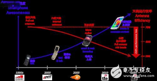
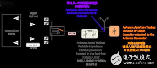
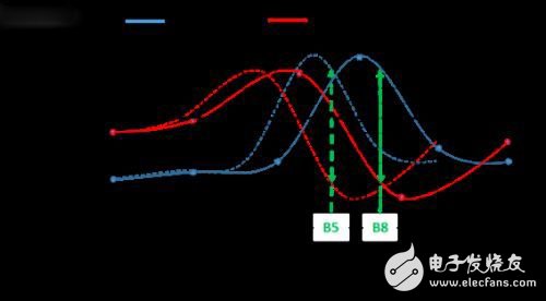
Global LTE smartphone shipments, network configuration and spectrum allocation are now growing rapidly, and the 3GPP Telecommunications Standards Organization has allocated more than 40 bands to the LTE standard. As the number of users and traffic continues to increase, major carriers such as AT&T (US) and Verizon (US) are beginning to adopt LTE-Advanced Carrier Aggregation (Carrier AggregaTIon) technology to increase the speed and capacity of the network. 3GPP has now identified more than 60 frequency band combinations, including in-band and inter-band aggregation. For this reason, smartphones need to optimize their technology to accommodate the increasing spectrum allocation scheme and the possibility of carrier aggregation. For LTE radios in mobile phones, this means that the radio must be able to "tune" any of these bands, which further requires the antenna to maintain high efficiency in all bands. However, it is easier said than done, and the design of antenna efficiency is far more difficult to set. In the early days of mobile phone production history, antennas were the last consideration for signal RF system designers. Early mobile phones were bulky and had low data rates, plus only four bands worldwide. These factors ensure that the high-signal performance of early mobile phones is not a problem. Fast forward to 2015, with large screens and large batteries becoming mainstream, and mobile phones have evolved into sophisticated smartphones. Original equipment manufacturers are increasingly adopting multiple antenna tuning techniques to ensure LTE signal performance over multiple frequency bands. Figure 1: Evolution of mobile phones and corresponding antenna efficiency The most critical aspect of LTE radio is the RF front end (RFFE), which includes antenna and analog data processing. The power amplifiers, filters, and power converters in the RFFE are designed to operate at the highest efficiency at 50 ohms—the target impedance of the antenna feed (antenna and RFFE connections). The antenna impedance of the antenna feed depends on the type of antenna. The most widely used in mobile device production is the dual-band PIFA antenna. In the resonant frequency, the feed point impedance of the antenna is pure resistance (approximately 90 Ω for a PIFA antenna, approximately 72 Ω for a dipole antenna, and approximately 36 Ω for a monopole antenna). In order to maximize the radiation efficiency, a simple fixed matching circuit can be used to match the impedance of the antenna to 50 Ω, thereby increasing the radiation of the input antenna power. Figure 2: LTE RF Radiation Front End (RFFE or Radio Frequency Front End) block diagram The industry now has two distinct antenna tuning methods: Adjustable Impedance Matching (TIM) Antenna aperture tuning Antenna Aperture Tuning (AAT) The use of tunable impedance matching requires the implantation of a variable matching network between the antenna and the receiver/transmitter. As the frequency changes, the impedance of the antenna changes, and the impedance of the antenna needs to be adjusted back to 50Ω required by the RFFE. This requires a closed loop system to monitor the incident and reflected power or measure the real and imaginary parts of the antenna impedance. Based on these measurements, the tuning elements of the matching network are adjusted, which in turn creates a new antenna feed point impedance to optimize power transfer. As for the antenna aperture tuning technique, a high Q variable capacitor is placed at an appropriate location on the radiating element. The load of the variable capacitor as the frequency changes will be dynamically adjusted such that the antenna resonant frequency matches the operating frequency. Matching the resonant frequency and the operating frequency is beneficial to keep the feed point impedance of the antenna relatively stable over the entire operating range, while a simple fixed network matches the impedance to the feed point target impedance of 50 Ω, thus ensuring the tuned antenna and RFFE Optimized power transfer between. To better understand the implementation of a typical PIFA antenna, the author will describe the real and imaginary parts of its impedance and explain how they change with frequency. Figure 3: Impedance performance of PIFA at different frequencies The PIFA antenna frequency shown in Figure 3 is adjusted to 920 Mhz (band B8), where the reactance is as close as possible to 0 Ω and the capacitance is as large as possible, about 90 Ω. The combination of high resistance and low inductance directly leads to good radiation efficiency - the optimum state of antenna tuning. However, if the PIFA antenna of Figure 3 operates at 860 MHz (band B5), it can be seen that the reactance significantly increases to nearly 60 Ω. The inductive effect of this antenna assembly hovers and does not radiate energy, thereby reducing the operational efficiency of the antenna. In addition, the antenna is heavily mismatched when operating in Band B5, reducing power transfer from the feeder to the inefficient antenna. The following explains how the two antenna tuning schemes optimize the performance of the PIFA antenna: The antenna aperture tuning scheme acts to vary the load of the variable capacitor and match the resonant frequency of the antenna to the operating frequency. The adjustment of the resonant frequency minimizes the impedance of the antenna (close to 0 Ω) and maximizes its resistance (close to 90 Ω). This allows the antenna to perform optimally anywhere in the spectrum, as shown by the dashed curve in Figure 3. In addition, ultra-low loss RF micro-motor system (RF MEMS) variable capacitors with less than 0.3dB insertion loss are now available for antenna aperture tuning techniques, further minimizing antenna emissions and minimizing power loss (concealed in RFFE) . The tunable impedance matching scheme measures the impedance of the antenna and adjusts the feed line to match the corresponding impedance, thereby optimizing the power conversion from the 50 Ω RFFE to the variable load presented by the antenna. However, impedance matching does not avoid the reactance characteristics of the antenna, which makes the antenna hoard the stored radiation and cannot fully utilize it. In addition, the most commonly used SOI or BST-based components in variable impedance matching networks can cause ohmic losses and produce large ("1 dB" insertion loss, which further limits power transfer optimization for tunable impedance matching. This article analyzes the two most common "antenna tuning" techniques available today. It has been found that the aperture tuning technique exhibits a double advantage compared to the following: Maintaining the resonant capability of the antenna while preventing the feed point from mismatching. This reliable, high performance, low loss RF MEMS "tuner" provides RF engineers and antenna designers with efficient antennas and low cost RFFE to create state-of-the-art smartphone RF devices. About Cavendish KineTIcs Cavendish KineTIcs () is the world's leading provider of RF MEMS antenna tuning solutions, providing high-performance antenna tuning solutions for smartphones, handhelds and portable devices. Cavendish's SmarTune equipment features the technical features of the MIPI RFFE interface, has passed the 100 billion cycle life test and has been in volume production since 2014. Cavendish Kinetics has offices around the world, including San Jose, California, China, Korea, Taiwan, and the Netherlands.
Laser Radar contains LSPD Safety Laser Scanner and LS laser radar. LSPD safety laser scanner is type 3 with CE certificate. It can be used for agv safety and industrial area protection. LS laser radar is for agv guide. Many famous agv manufacturers has installed LS laser radar to guide their agvs. Our cooperating brand contains Quicktron, Mushiny, Aresbots, etc. Feedback from customers are quite posotive.
Laser Radar Laser Radar,Auto Guided Vehicle Guide Radar,Sick Laser Radar,Safety Scanner,Safety Laser Scanner,Ls Series Laser Radar Jining KeLi Photoelectronic Industrial Co.,Ltd , https://www.sdkelien.com