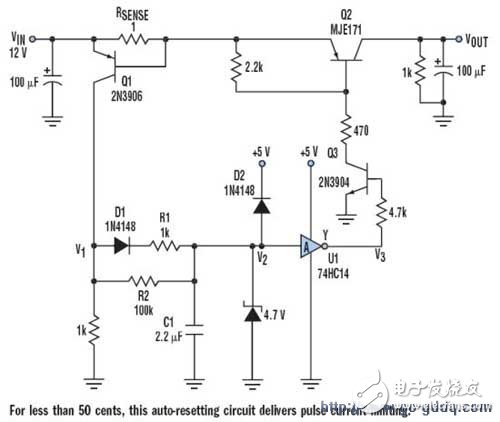
Protection of auxiliary output power circuit diagram with automatic reset circuit
Many devices require an auxiliary DC output to power external components or subsystems. When these subsystems are thermally connected, it's crucial to protect the auxiliary outputs from short circuits. Traditional fuse-based solutions are slow and can cause a voltage drop on the internal DC rail, potentially disrupting the main system.
A more efficient approach uses pulse current to limit damage while keeping costs low. This method can handle both transient and continuous short circuits. The impact on the input is minimal—just a small glitch of a few hundred millivolts over hundreds of microseconds. The circuit includes U1 as a Schmitt trigger inverter (74HC14), Q2 as a switch, and RSENSE as a current-sensing resistor. It operates with VIN = 12 V and is designed for up to 0.6A of load current.
Under normal conditions, when the load current is below 500mA, Q1 remains off, V1 and V2 are at 0V, C1 is discharged, and V3 is at 5V. Q3 and Q2 are active, so VOUT stays at 12V.
If the load current exceeds 0.6A, Q1 turns on, causing V1 to rise. C1 charges through D1 with a small time constant (C1 × R1). When V2 surpasses the upper trip point of the 74HC14, V3 drops, turning off Q3 and Q2, which cuts off the load current. Then, Q1 turns off, V1 decreases, and C1 discharges through a larger time constant (C1 × R2). After a longer delay, V2 falls, V3 rises again, and Q2 opens the circuit.
If the short persists, the pulse switch cycles on and off continuously. For high-current applications, power loss on RSENSE can be significant. To address this, Q1 can be replaced with a high-side current sensor that includes amplification, such as the ZXCT1021 from Zetex, with appropriate circuit modifications. D2 serves as a protection diode to discharge C1 when power is turned off. Q2 has a high current rating (4–5A). Designers should also consider the tolerance of the Schmitt trigger’s trip point. Q2 can be swapped with a P-channel MOSFET to reduce the forward voltage drop. For higher voltages like 24V, the gate-source voltage of the MOSFET must be protected to avoid exceeding the Zener breakdown voltage.
When the output is shorted by a 1Ω resistor, V2 generates a sawtooth waveform between 2V and 3.2V, with a rise time of 500μs and a delay of 1 second. The peak current pulse is about 1.5A for 500μs, while the input disturbance is approximately 0.2V for the same duration. Using a smaller C1 value, such as 0.47μF, can reduce the pulse width of the short-circuit current.
9000 Puffs Disposable Vape,7000 Puffs Disposable Vape,9000 Puffs Vape
Longhua Manxueling Trading Company , https://www.mxlvape.com