Discussion on Intelligent Solution of Large Digital Monitoring System
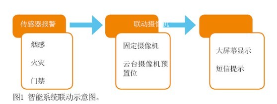
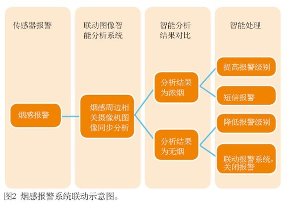
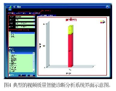
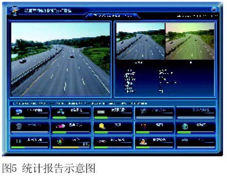
The original intention of monitoring system construction is to "seeing is believing", but for the various analog and digital monitoring systems currently seen, it has not realized the true meaning of "seeing is believing". In other words, even if the real-time or storage implementation is different, the large-scale monitoring system does not jump out of the “real-time + storage†monitoring standardization model. This article refers to the address: http:// Intelligent information linkage The information source of the monitoring system is image information, while the information source of other security systems (such as access control, fire alarm, etc.) is sensor information. In most of the current large security system construction, most of the information can be linked, and generally After the sensor generates the alarm information, it provides the linkage to the monitoring system, and then switches the corresponding image information to the display device (as shown in Figure 1). The above solution can be illustrated by an image metaphor: the monitoring system is the human eye, the alarm system is the human hand, and when the hand feels that something is wrong, the head automatically turns to look. However, the head automatically turns over, just a conditional reflection. The results seen must be analyzed by the brain. That is to say, this solution is not perfect, it lacks the intelligent analysis part. The process of optimizing the linkage analysis should be provided to the monitoring system by the sensor to generate the alarm information, and switch the corresponding image information to the linkage analysis system. The linkage analysis system intelligently analyzes the image information and the alarm information, so as to eliminate the false alarm information, and The false alarm signal is sent back to the alarm system by the monitoring system. In this scheme, the linkage information relies on intelligent image analysis technology, and the intelligent analysis system currently uses target behavior analysis and feature analysis. For example, in the case of a smoke detector that frequently generates false alarms, when an alarm occurs in the smoke detector, the alarm signal is sent to the intelligent digital video system through a dry contact or other means, and the image content is simultaneously performed on the single or multiple camera images surrounding the smoke sensor. Analysis, when the analysis result is determined to be thick smoke, the feedback information is sent to the alarm system to raise the alarm level, prompting the management personnel to pay attention to the problem; and when the analysis result is determined that the image is normal, the feedback information is sent to the alarm system, and the prompt is false alarm. You can choose to turn off the alarm or lower the alarm level to manually turn off the alarm (Figure 2). Intelligent operation and maintenance management system Due to the large number of monitoring systems, management and maintenance personnel can easily grasp the operating status of the system. It is more and more difficult for the system operation management to understand and master the health status of the overall system operation. Many problems are often found in the application. ,E.g: · A camera has no image; · The camera monitors the image to shift; · The image of the camera is not clear; · The video of the camera is not recorded; · The device network is unreachable and so on. The existing large-scale CCTV system basically relies on manpower to discover defects in video quality, and checks whether the stored video is normal. The technicians actively test the underlying network communication status to determine whether the video transmission network is normal or whether there is a bottleneck. There are many shortcomings: · People's visual experience finds video quality problems, there are many uncertain factors; · When the number of cameras reaches hundreds of thousands, the manpower is basically not feasible; · It is very difficult to find out whether the stored video is normal or not. ·Manual way to check the operating status of the system, unable to achieve comprehensive inspection and daily inspection of the overall system; · Lack of professional quantitative analysis reports; • The overall operating status cannot be provided in real time. In short, there is a very big omission in the existing CCTV system: there is a lack of powerful system tools to check whether the overall CCTV is in normal operation. This paper proposes an intelligent diagnostic analysis system, which is used to complete most of the monitoring system's later operation and maintenance work, and the system is not for single mode or single brand, it can be compatible with the current 90% or higher surveillance system - Video quality intelligent diagnostic analysis system. IDAS collects video, network device related data through the running video surveillance network, tests related signals, analyzes video quality, and timely and comprehensively understands the operation of the video network, and quickly and effectively diagnoses a huge video network monitoring system. A management system that objectively evaluates the health of the system operation and achieves overall management of the system. The main problems solved are as follows: · Timely discovery of various equipment failures in the CCTV system; · Forecasting and suggesting potential failures; · Provide real-time operational status reports for the system as a whole; · Remote inspection and diagnosis. This solution contains a variety of application technologies (as shown in Figure 3), which has certain system meaning: · It is a system tool for checking the overall health of the CCTV system; · Provide professional system operation status report, which is the data support of system maintenance planning; · Fill in the gaps in the self-checking of CCTV system operating status. The system mainly consists of three parts: detector, supervisory server and operation display terminal. detector Through real-time intelligent analysis of dynamic image images, the detector collects business data and business status of video and video equipment in the area, thereby discovering system problems and diagnosing system working conditions. The operation of the detector is not dependent on the specific equipment. The working process of the detector can be flexibly configured, so that all system equipment can be rotated and inspected in time from the perspective of the video application. Main business module: · Real-time video service analysis module; · Video video service analysis module; · Video equipment business status management module; · Recording equipment business status management module; · Network transmission quality analysis module (network equipment operating status / network transmission jitter); · Diagnostic result management module, the detector should store the diagnosis result and upload it to the supervision server in real time; if the supervision server is unavailable, check the supervision server regularly; when the supervision server is available, re-upload the diagnosis result; · The historical diagnosis result inquiry module provides query for the historical diagnosis result of the detector, which can be performed according to conditions such as camera, coding equipment, alarm time, alarm type (Fig. 4 is a typical video quality intelligent diagnosis and analysis system interface). Typical video quality intelligent diagnostic analysis system interface • The supervisory server aggregates the test results of each detector to provide valid data for the overall assessment and diagnosis of the monitoring system. Distribute the diagnostic information of the detector to the operation display terminal. The automatic mail notification system can perform statistics according to days, weeks, and months, and send the statistical results to the relevant responsible person. · Obtain data from the detector and save it to the local database for processing and analysis. It can manually refresh or force refresh the video network data. Equipment information management, including management of cameras, encoding equipment, decoding equipment, video equipment, and detectors; · Detection plan management, setting which devices the probe detects, what functions to detect, and when to probe; · Diagnostic result management, receiving the diagnostic results of the detector, and depositing the diagnosis results into the database on a daily basis; Real-time diagnostic results distribution, distributing diagnostic results to designated clients; · History diagnosis result query function, you can query all historical diagnosis results of all detectors, and can query according to the conditions of detector, camera, coding equipment, alarm time, alarm type, etc. ·User Management; · System log management; · Support multiple databases, through configuration to achieve access to different databases. Operation display terminal Manage the entire network of devices, present real-time diagnostic information, real-time alarm display, historical diagnostic information, etc. to the user. ·Camera management; · Configure related parameters; · Configure the basic parameters of the detector; · Configure the detector's detection plan; · Configure the distribution plan of the supervisory server; ·Multi-user and rights management; · Display diagnostic results in real time; ·Repair Order; · alarm shielding; · Statistical report (Figure 5); · Report export and print; Statistical report diagram · System log query. Through the system, in the venue application, the following functions can be realized: · Video detection of the front-end device; · Video loss and black frames; ·Automatic aperture failure; ·Automatic/manual focus failure; · Achromatic; · Scene changes; · Video distortion; · image interference; · Image color cast; · Status detection of the video device; · Codec equipment; ·IPCamera; ·DVR/NVR; · network equipment; · d1 detects network equipment; · Network equipment operating status; · Transmission network dropped packets; · Network transmission jitter; · Detection of video equipment; · Video quality detection (image defect or low quality); · Storage space detection (storage capacity critical / insufficient); · Recording status detection; · Automatic inspection. For operation and maintenance managers, the system can also provide professional analysis reports. Through the operation of the detector, various types of system detection data are generated, and the overall operation status report of the system can be provided in real time, so that the system administrator can understand the official operation status of the CCTV system in real time, and grasp that the operation fault has existed or will occur. The equipment and links provide detailed data reporting support for the system administrators, so that they can make maintenance predictions and plans for the system. · the operating status of the equipment; · the quality of the video; · the quality of the video; · Network transmission quality; · the overall health of the video system; · Maintenance recommendations and retrofit/expansion recommendations. This system can be deployed centrally in a CCTV system network or distributed (mainly detectors). Distributed deployment can deploy detectors in multiple different network segments. The advantage is that the bandwidth of video traffic across network segments can be reduced. The system can configure the number of video streams for concurrent detection in the interval of convenient configuration detection, so that flexible configuration can be performed according to the total number of video streams of the CCTV system and the network withstand bandwidth, combined with the user's inspection interval requirement. In order to achieve the goal of detecting the video stream of all CCTV systems at a timing. Conclusion As a network digital video surveillance system that relies on IP networks as a carrier to develop rapidly, its subclass inherits the relevant characteristics of the parent class, making it extremely promising. The article reviews and draws on the development history of IP networks, so it is foreseeable that scientific and intelligent video network management will eventually become a "self-contained" and develop into a perfect solution. At the same time, major manufacturers will also strive towards the standardization of the industry. I hope this article can “bring the bricks to attract jadeâ€, so that the industry work can really develop into the upper application of rich video systems, and promote the rapid and healthy development of the digital video industry.
1.2L Food Choppers since they are moderate in size, many people will choose them. They not only can chop vegetables, but also can chop a lot of meat. And 1.2L food choppers have glass bowl and stainless steel bowl optional.
Description for 1.2L Food Choppers
300W/350W
with dobule blades
1 speed easy to control
Carton box: 60.5*41*26.5cm 6pcs/ctn
20'GP: 2646pcs 40'HQ: 6294pcs
1.2L Food Choppers 1.2L Food Choppers,1.2L Choppers,Best Food Chopper,Glass Food Chopper Machine Flying Electronic Co., Ltd , https://www.flyingelectronic.com