Application of Machine Vision in Fiber End Face Defect Detection
Abstract: The traditional fiber end face defect detection uses manual detection. This method is very inefficient and the subjectivity of the test results is very strong. The use of machine vision inspection for fiber end face defects can greatly improve detection efficiency and detection accuracy. First, the acquired image is binarized by image processing, and then the center of the core is positioned, and then the ring end of the fiber is divided into different ring detection regions by the center of the core. Since the defects on the end face of the fiber may be dark or bright, in order to distinguish between the two, different binary processing is required for each region detection. If there is any area, the detection cannot pass. Then the fiber end face is not satisfactory. The results show that the use of machine vision for fiber end face detection can quickly and accurately detect the location and size of the defect. This article refers to the address: http://
Quickly brew the perfect
cup of tea or make pour over coffee right at the table with the Electric Tea
Kettle. With 1500 watts, this Electric Kettle boils water faster than a
microwave, and is safer to use than a stovetop kettle because it automatically
turns off when the water reaches a boil. Serving at the table is no problem as
the kettle lifts off the base without the cord. Additional features include two
water level windows and a pull-lid to make filling and serving easy.
Features:
Application:
Heat
the tea thoroughly
Bottle
the water/beer
Boil
water
Electric Tea Kettle Electric Tea Kettle,Stainless Steel Electric Tea Kettle,Cordless Electric Tea Kettle,Electric Cordless Glass Tea Kettle Guangzhou Taipeng Electrical Appliances Technology CO., LTD. , https://www.taipengelectric.com
Key words: fiber end face; machine vision; defect detection; image processing
0 Introduction As a carrier of the information superhighway and an important part of the optical fiber communication system, the optical fiber represents a very superior information transmission characteristic and is an indispensable element of the information society in the 21st century. In fiber-optic communication, the active connection of the fiber is achieved through the fiber optic connector, and the cleanliness of the fiber end face has a decisive influence on the performance of the connector. In addition to permanent damage (such as scratches and cracks) on the end face of the fiber during the polishing process or during online business operations such as fiber insertion and removal, it may be associated with unclean hands, fiber cap edges, and methods during normal use. The metal edge of the blue plate, the dirty fiber end face, and the contact of particles in the air, the fiber end face is also subject to various temporary pollution (such as dirt, oil, water or detergent residue), so that its performance is affected. This not only causes the connection loss to become large, but also deteriorates the communication performance. In severe cases, the core is blocked and cannot transmit light, thereby causing the core to be burned by the high-power laser. In order to ensure the stability and efficiency of fiber communication, the end face of each fiber must be cleaned to a certain extent.
The traditional fiber end face defect detection method uses a manual detection method. This method first collects the image of the end face of the fiber, and then observes the dirt with the naked eye, and then manually determines. Since this method is such that the examiner continuously observes the end face of the optical fiber, it is easy to cause visual fatigue, so the efficiency is relatively low. Moreover, each person's experience and responsibility are different, and the quality of the products obtained will vary considerably. In order to improve product reliability and production efficiency, this paper proposes a method of discarding artificial naked eye detection and using machine vision for detection. Machine vision mainly uses computers to simulate human visual functions, extracts information from images of objective things, performs image processing and understanding, and then uses for defect detection of fiber end faces. Compared with manual detection, the machine vision detection method improves the detection accuracy, reduces the test cost, enhances the test capability, makes the training of the operators on the production line less difficult, and can obtain more production line monitoring data information.
This article describes how to use machine vision for defect detection of fiber end faces and completes the development of machine vision systems using National Instruments (NI)'s VBAI vision automatic inspection development environment. VBAI (Vision Builder for Automated Inspection) is a visual inspection software developed by NI as a visual generator for automatic detection. This tool is the ideal tool for rapid visual effects verification in the laboratory and is a good production line simple test platform. The results show that the system can detect the location and size of the defect more accurately, and the speed is faster, which meets the requirements for fiber end defect detection.
1 Detection system The fiber optic end defect machine vision inspection system proposed in this paper consists of a fiber end face detector and a PC system. At the time of detection, the fiber optic patch connector is inserted into the fixed test platform of the fiber end face detector, and the fiber end face detector is connected to the PC system through the USB cable, so that the image can be collected into the computer. Adjust the focal length of the microscope. Once a satisfactory image is obtained, start the software to analyze the end face of the fiber and compare it with the standard indicators preset by the software to quantitatively determine the information of each area and judge whether the end face of the fiber is qualified or not.
The detection performance of the system is related to the software's ability, microscope performance, and the skill of the operator to focus the image. It has been proven to be superior to manual detection in terms of accuracy, repeatability, reproducibility, and detection efficiency. The program can also provide specific records of test results, including end image and damage detection data, to improve the automation of the system.
2 Detection process The detection software used in this system is developed based on the VBAI visual automatic detection development environment, and has the ability to process and analyze the fiber end image. The processing flow is shown in Figure 1. 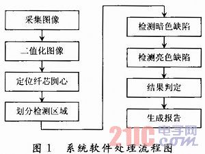
When using the fiber end face detector to image the fiber end face, since the position of the fiber end face in the field of view is different each time, the position of the fiber end face core must be positioned first. Detection. To position the core, you first need to binarize the acquired image. Because the initial image acquired by the fiber end face detector is 32-bit, and the function module for image analysis and processing in VBAI basically does not support 32-bit images, only the 32-bit image is converted into a binary image. A series of accurate analyses can be performed on it. The initial image is image processed using VBAI's Vision Assistant function module. A grayscale 8-bitmap can be obtained by extracting a sub-function of the color value (Extract HSL), and then the image is binarized using the threshold method.
The threshold method is a simple and effective image segmentation method. The method uses one or several thresholds to divide the pixel gray level of an image into several levels, and pixels belonging to one level are considered to be the same type of object. It should be noted that in the process of detecting the end face of the fiber, since the cladding layer may belong to the same gray level as the dirt outside the cladding layer, the cladding layer cannot be simultaneously detected when the contamination outside the cladding layer is detected. If the dirt on the surface is detected, the cladding layer needs to be shielded and then detected.
In this system, let F(x, y) denote the output of binarization of the image, the pixel gray level range is [a, b], and only one a and b need to be set for the same type of defect detection. The threshold TH between the images divides the pixels of the image into two groups of pixel groups (defects) larger than TH and pixel groups (background) smaller than TH. which is: 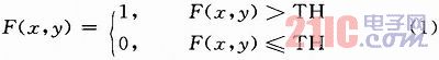
Image binarization sets the gray value of the defective pixel to 0, and the gray value of the background pixel to 1. In VBAI's visual assistant function module, there is a function sub-module that sets the threshold (Threshold). When calling, you only need to find the peaks and troughs according to the bimodal method on the threshold histogram, and manually adjust the threshold to make it Defects are distinguished from the background, as shown in Figure 2. 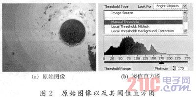
2.1 Core Positioning The method used to locate the fiber core is to find the entire cladding of the fiber. Since the shape of the fiber cladding is a circle, the center of the circle is the center of the core. If there is a large degree of pollution on the end face of the fiber, if the image is binarized only by setting a certain threshold, the obtained binary image may have a lot of dirt in addition to the fiber cladding, so that the positioning of the fiber cladding is generated. Great impact. So after binarizing the image, you need to use some sub-function modules in the visual assistant to perform some morphological processing on the image, using the two functions of RemoveSmall Objeets and Remove Large Objects. The module adjusts the number of iterations to filter out particles smaller than the fiber cladding and larger than the fiber cladding, thereby removing the interference to the fiber cladding positioning, so that only the image of the fiber cladding is obtained in the binary image. As shown in Figure 3. 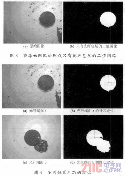
After obtaining the binary image of the fiber cladding layer, the function module of the Find Circular Edge and the Set Coordinate System in VBAI can be used to accurately locate the position of the fiber core. Looking for the rounded edge is to find the edge of the fiber cladding circle, so to find the center of the fiber cladding circle, this center is also the center of the core circle, and then use this center as the coordinate system origin to establish the coordinate system. In VBAI, the function of establishing the coordinate system is the positioning feature, which can automatically locate the center of the circle according to the found cladding circle. Even if the position of the cladding changes in the image, the origin of the coordinate system can be accurately positioned in the cladding circle. On the center of the circle, the center of the cladding circle is the center of the core circle. As can be seen from Fig. 4, the origin of the coordinate system can be accurately positioned on the center of the core circle of different positions, even at the irregular packet level.
2.2 Division of detection area After the fiber core is positioned, since the detection standards used in different ring ranges on the end face of the fiber are different, it is necessary to make the ring of different areas with the core center as the center, and then Within the ring, the test is carried out according to the specified test standards. If the detection in any of the rings fails, the fiber is defective and cannot pass. When dividing the area, the image acquired by the fiber end face detector is measured in pixels (pix) in the VBAI environment, and the fiber end face detection requirement given in the general detection standard is in micrometer (μm). The unit of measurement, so the conversion of the formula (2) to convert the micrometer (μm) into pixels (pix). When converting, you need to know a parameter: dpi (how many points per inch). If you know dpi, you can get the pixel-to-micron conversion relationship from formula (2). Let P be the pixel, D be dpi, I be feet, and M be micron, then: 
The dpi of a picture can be obtained by some commonly used graphics software (such as Acdsee, Photoshop, etc.). The standard resolution dpi of 640×480 or 800×600 is a constant: 96. In this way, when the fiber end face is divided into regions, the diameter of each ring can be accurately calculated, so that the entire fiber end face can be carefully and accurately detected.
2.3 Detection of defects
2.3.1 Different Thresholds Fiber end defects include white spots (collapse), black spots (dirty), shadows (inner cracks), and scratches. Among them, the collapse and the scratch are the portions where the color is brighter on the end face of the fiber, and the dirt and shadow are the portions of the color darker than the end face of the fiber. To detect these defects, the original image should be re-imaged before each bright part of each area is detected, and the original image should be re-imaged before each dark part of each area is detected. In order to set different thresholds to distinguish the portion brighter than the end face of the fiber and the portion darker than the end face of the fiber. In this way, the dark part and the bright part are detected successively during the detection process. If any of the two tests cannot pass, the detection of this area cannot pass.
The area where the end face of the fiber needs to be inspected includes the ceramic cladding except the fiber cladding and the fiber cladding, so bright and dark defects may be distributed on the ceramic surface in addition to being distributed on the fiber cladding. Since the fiber cladding is dark in the acquired image, it is closer to the darkness of the defect, and the ceramic portion outside the cladding is closer to the defect of the bright color. Therefore, when detecting defects on the fiber cladding layer and on the ceramic surface outside the cladding layer, different threshold values ​​are required for dark color defects and bright color defects, so that the defects of the entire end surface can be accurately detected. Therefore, when using VBAI to detect the ceramic surface area outside the fiber cladding, it is necessary to set the threshold according to the bimodal method again, as shown in FIG. 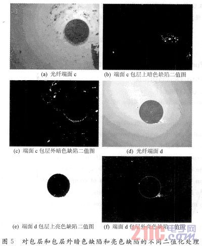
It can be seen from Fig. 5 that in the process of detection, different thresholds must be set for the different distributions of dark defects and bright color defects in the inner and outer layers of the fiber end, otherwise the accuracy of the detection will be greatly affected. It should be noted that the core itself is bright, so the core needs to be ignored during the detection of bright color defects.
2.3.2 Determination of Defects In the detection of fiber end face defects, there are both unacceptable defects and acceptable defects. For defective particles such as collapse, dirt, internal cracks and scratches, can they be identified as being Acceptance depends on their size and length. In general, the size and length of their evaluation are mainly based on the size of their Feret Diameter. The Ferret diameter is a commonly used method for expressing particle diameters. For regular spherical particles, the "diameter" can be used to accurately describe the size. However, in most cases, the shape of the particles, especially the scratches, is not spherical. It is obviously unclear and it is easy to cause misunderstanding. Therefore, the concept of particle size refers to the concept of "particle diameter". The so-called particle diameter, which is the "one-size" size of the particle size. "Dimensions", also known as dimensions, are units of measurement of basic physical quantities, such as length, volume, quality, time, and so on. The same particles, due to different applications, the measurement methods are often different, the value of the obtained particle diameter is of course different, such as: under the microscope, the size of the particles in the plane perpendicular to the line of sight, the screening obtained The particle size is the size of the mesh, and the sedimentation results in the diameter of the spherical particles having the same sedimentation characteristics.
In the fiber optic end-face defect machine vision inspection of this paper, the Feret diameter of the defect to be measured after binarizing the image is the size on the plane perpendicular to the line of sight under the microscope. The Feret diameter of any irregular object is large or small, and usually the maximum Feret diameter is required, and then compared with the test standard. If the maximum Feret diameter is larger than the acceptable defect particle diameter, Then the test cannot pass. VBAI is very powerful, it provides a function to directly measure the Max Feret Diameter, which makes it easy and quick to measure the maximum Feret diameter of various defective particles, including linear features. The maximum Feret diameter of a scratch or scratch is its length. In VBAI's visual assistant function module, there is a sub-function module of Particle Filter, which can set a certain range of maximum Feret diameter values, and then the defective particles with the maximum Feret diameter in this range are The filtration is carried out, and then the determination is made. For example, in one detection area, the number of defective particles requiring a maximum Feret diameter of 5 μm or less cannot exceed 5, and no defective particles larger than 5 μm are required. Using equation (2), it can be calculated that 5 μm is converted to a pixel value approximately equal to 7.559 pix after a magnification of 400 times. Then, using the particle filter function module, the defect particles with a maximum Feret diameter less than 7.559 pix are first filtered, and the number of particles is detected by a particle analysis (Detect Objects) function module. If particles are detected, the determination cannot be passed; then reuse The particle filter function module filters the particles with a maximum Feret diameter greater than 7.559 pix, and still uses the particle analysis function module to detect the number of particles. If more than 5 particles are detected, the determination cannot pass.
After detecting all the areas, call the Set Inspection Status function module in VBAI. There is an option to "If any of the detection steps cannot pass, then this test cannot pass (Fail if Any Previous Step Fails) "When this option is selected, if the detection of any of the previous areas cannot pass, the detection of the end face of the fiber is judged as not passing, so that no detection area that does not meet the detection requirements will be missed.
2.4 Report Generation Reports are the most intuitive and important credentials for verifying test results and are an integral part of the test system. After the fiber end face inspection is completed, a lot of data is generated, including the number and size of defects in each detection area. If these data are automatically imported into Excel or Word files after specifying the file path, not only can the automation of the entire detection system be improved, but also the workload of the tester is greatly reduced. So at the end of the program, add a Data Logging function module in VBAI, save the data in Excel format on the hard disk of the local computer or upload it to the FTP server and save it to improve the security of the data. Reliability, easy to view at any time.
3 Conclusions In this paper, based on the image processing technology, a set of optical fiber end face defect detection system based on machine vision is developed. It is proved by experiments that this system can detect defects of fiber end face with high efficiency and high quality. Judging, avoiding the operational errors caused by manual detection, greatly improving the reliability of detection.
In addition to the application of fiber end face detection in this paper, with the high-tech detection technology such as infrared, ultraviolet, X-ray, and ultrasonic, machine vision has its outstanding advantages in detecting non-visual objects and high-risk scenes. Therefore, machine vision inspection will become an increasingly popular solution.