Avionics automatic test system? Hand over to the virtual instrument!
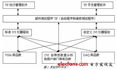
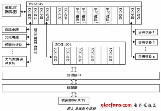
System hardware design: Compared with GPIB, VXI, RS232 and other instruments, PXI modular instruments have the advantages of high speed, small size and easy expansion. Therefore, PXI modular instruments are mainly used in hardware, and conventional signal source (SOURCE) and signal measurement are selected. The module (SENSOR) expands dedicated and self-developed equipment via GPIB and RS232 buses. The system hardware schematic is shown in Figure 1. Due to the large number of PXI modules and the future expansion, the 18-slot PXI-1045 chassis was selected. In order to further improve the integration of the system platform, the PXI-8187 zero-slot embedded controller was selected, and the use of MXI in the previous system was abandoned. -2 The industrial computer is used as the main controller. The PXI-8187 has a GPIB interface, which can easily expand the GPIB bus device. Some instrument resources and components require serial communication, so the PXI-8421 is used to expand four serial ports. Signal acquisition The 6 1/2 digital multimeter PXI-4070 and the 5 1/2 digital multimeter PXI-4060 are commonly used as test modules for measuring voltage, resistance and current. They can measure 0-300V voltage and 0-1A current. 0-100M ohm resistor; Oscilloscope PXI-5112 (2 channels, 8 bits) Resolution, 100MHz bandwidth) and analog input PXI-6070E (16 single-ended input / 8 differential input, 12-bit resolution, 1.25M sampling rate) can be used to meet the commonly used continuous wave and single point voltage signal acquisition When the PXI-6070E is used for data acquisition, two SCXI-1125s are connected to the front end for signal conditioning (10Khz or 4Hz low-pass filtering, attenuation). The PXI-6070E is also used for communication between the controller and the SCXI chassis. The high-speed DIO PXI-6534 can acquire and output high and low speed discrete quantities. Special and complex signals are collected and processed using GPIB equipment and RS232 self-developed equipment such as spectrum analyzers. 2. Signal output Function generator PXI-5421 (16-bit resolution, 100MS/s sampling rate, bandwidth 43MHz) and high-speed analog output PXI-6733 (8-channel output, 16-bit resolution, update rate 1MHz) can be used to meet common continuous Wave and single point voltage signal output; SCXI-1124 is used to isolate the output of analog voltage and current. Special and complex signal outputs use GPIB equipment and RS232 self-developed equipment, such as AC and DC power, RF signal source, atmospheric data test system, simulator and so on. 3. Signal routing Since most of the onboard electronic devices have a large number of signals, it is impossible to connect all signals directly to the resources at the same time, and must be switched through the relay matrix. The relays must have a fast response time and can switch large signals, so we Two relay matrix modules SCXI-1129 and accessories SCXI-1333 and SCXI-1339 are selected to form a suitable relay matrix (maximum on-off capability 150VDC/1A, 150Vrms/250mA). In the process of connecting and disconnecting signals, in order to realize the automatic selection and safety protection of the optimal path (avoiding the source connection), we have rewritten the relay matrix drive and achieved satisfactory results in actual use. 4. Resource interface and adapter A resource interface is a collection of all resource interfaces, and each component connects some resources through an adapter as needed. One or more UUTs share an adapter, so the test system can configure one or more adapters based on the signal conditions of the UUT. System software design: CVI is a virtual instrument development software that adds instrument control and tool function libraries to the standard C language (ansi C). It provides many practical routines, has a friendly graphical user interface, and C language is familiar to everyone. And easy to use development environment, so the choice of CVI can speed up the development of test procedures (TP). The system software principle is shown in Figure 2. In order to facilitate and standardize the writing of the TP, the TP development management software automatically generates the test program code framework and the instrument operation code according to the input test information. After the test program is written, the dynamic library is compiled and generated, and the test program executes the management software call and manages the test program. During the development of the test program, the development of instrument operation and virtual instrument interface is the two main points. Fiber Optic Adapter / Fiber Optic Coupler Fiber To Ethernet Converter,Optical To Ethernet Converter,Optical Fiber To Ethernet Converter,Fiber Optic To Ethernet Converter Price Ningbo Fengwei Communication Technology Co., Ltd , https://www.fengweicommunication.com
