Step by step market refinement of white LED and other applications
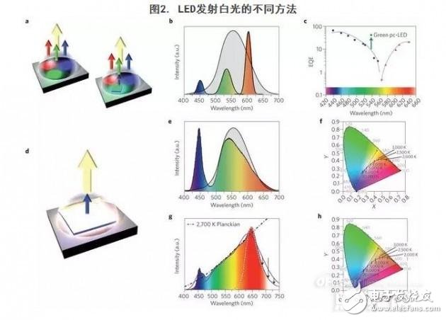
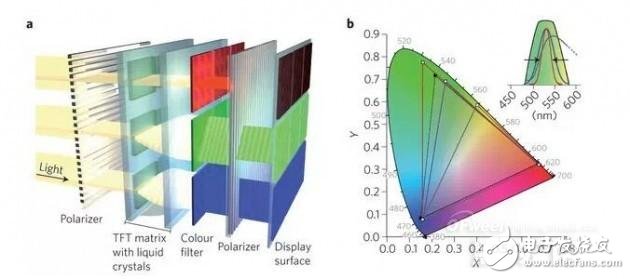
Recent advances in light-emitting diodes (LEDs) have led to a rapid growth in the lighting industry. At present, solid-state lighting technology has gradually penetrated into different market segments, such as automotive lighting, indoor and outdoor lighting, medical applications, and household items. According to the latest report of the US Department of Energy, by 2020, the technology is expected to reduce energy consumption by 15% in the lighting industry, saving 30% in 2030 – that is, saving 261 TWh (terawatt hour) of energy in 2030, with current The price is calculated at more than $26 billion, which is equivalent to the current total energy consumption of 24 million American households. In addition, these savings in energy used in hybrid power plants will reduce emissions of approximately 18 million tons of CO2 greenhouse gases. Although in many cases the initial cost of these devices is still higher than existing light source devices, the higher efficiency and longer life of LEDs makes them highly competitive. Strategies Unlimited estimates that 400 million LEDs will be sold worldwide in 2013. The McKinsey survey indicates that LEDs will have a 45% share of the global general lighting market in 2016 and close to 70% in 2020. By 2020, market capacity in this area is expected to increase from the current $26 billion to $72 billion. The LED device is a complex multi-component system that adjusts performance characteristics to specific needs. The following sections discuss white LEDs and other applications. LED development path The electroluminescence phenomenon in inorganic materials is the basis of LED luminescence. HenryRound and Oleg Vladimirovich Losev reported LED luminescence phenomena in 1907 and 1927 respectively - current passing through makes silicon carbide (SiC) crystals emit light. These results have led to further theoretical studies of semiconductor and pn junction optoelectronic processes. In the 1950s and 1960s, scientists began to study the electroluminescence properties of Ge, Si, and a series of III-V semiconductors (such as InGaP, GaAlAs). Richard Haynes and William Shockley demonstrated that electron and hole recombination in the pn junction leads to luminescence. Subsequently, a series of semiconductors were researched, and in 1962, the first red LED was developed by Nick Holonyak. Affected by it, George Craford invented orange LEDs in 1971. In 1972, yellow and green LEDs (both made up of GaAsP) were invented. Intense research has rapidly commercialized LEDs that illuminate over a wide spectral range (from infrared to yellow), primarily for indicator lights on phones or control panels. In fact, these LEDs are very inefficient and have limited current density, making the brightness very low and not suitable for general illumination. Blue LEDs The development of high-efficiency blue LEDs took 30 years because there were no wide-bandgap semiconductors of sufficient quality to be applied at the time. In 1989, the first blue LEDs based on SiC material systems were commercialized, but because SiC is an indirect bandgap semiconductor, its efficiency is very low. Direct bandgap semiconductor GaN was considered in the late 1950s, and in 1971 Jacques Pankove demonstrated the first green-emitting GaN-based LED. However, techniques for preparing high quality GaN single crystals and introducing n-type and p-type dopants into these materials are still to be developed. Technologies such as metal-organic vapor phase epitaxy (MOVPE) developed in the 1970s are a milestone for the development of high-efficiency blue LEDs. In 1974, Japanese scientist Isamu Akasaki began to grow GaN crystals in this way, and in 1986, in cooperation with Hiroshi Aman, the first high-quality device-level GaN was synthesized by the MOVPE method. Another major challenge is the controlled synthesis of p-type doped GaN. In fact, in the MOVPE process, Mg and Zn atoms can enter the crystal structure of this material, but often combine with hydrogen to form an ineffective p-type dopant. Amano, Akasaki and co-workers observed that Zn-doped GaN emits more light after scanning electron microscopy. In the same way, they proved that electron beam radiation has a beneficial effect on the doping performance of Mg atoms. Subsequently, Shuji Nakamura proposed to add a simple post-deposition step after thermal annealing to decompose the complexes of Mg and Zn, which can easily achieve p-type doping of GaN and its ternary alloys (InGaN, AlGaN). It should be noted that the energy bands of these ternary systems can be adjusted by the composition of Al and In, which adds a degree of freedom to the design of blue LEDs, which is of great significance for improving its efficiency. In fact, the active layers of these devices currently consist of a series of alternating narrow bandgap InGaN and GaN layers and a wideband p-type doped AlGaN film (as a p-terminal confinement of carriers). In 1994, Nakamura and its collaborators demonstrated the GaN double-heterostructure with Zn-doped InGaN active layer between n-type and p-type doped AlGaN, demonstrating for the first time an InGaN blue light with 2.7% external quantum efficiency (EQE). LEDs (Box 1 lists the main performance metrics for LEDs). A schematic of the LED structure is shown in Figure 1a. These results are critical to today's LED-based lighting technology and have led to a revolution in the lighting industry. At the end of 2014, the Nobel Prize in Physics was awarded to Akasaki, Amano and Nakamura for their “invention of efficient blue LEDs for lighting and white light source energy savingsâ€. LED performance indicators Quantum efficiency: The quantum efficiency (IQE) within a material is the ratio of the number of electron-hole recombination (ie, photons produced) to the total amount of recombination (radiation versus non-radiation). This indicator determines the luminous efficiency of semiconductor materials. Semiconductor LED performance is typically expressed using external quantum efficiency (EQE), the product of IQE and extraction efficiency. The extraction efficiency specifically refers to the portion of the generated photons that escapes from the LED. EQE depends on semiconductor layer defects that directly affect IQE and device configurations that affect extraction efficiency. Luminous efficacy: Luminous efficiency is the efficiency of the light source to emit visible radiation. The unit is generally lm W? 1. The light source converts 100% of the energy with monochromatic green light (frequency of 4501012 Hz, corresponding wavelength of about 555 nm, the most sensitive light of the human eye, Figure 2b is the corresponding eye sensitivity curve), and its maximum luminous efficiency reaches 683 lm W? 1. White light sources for illumination typically require a broader emission spectrum than the entire visible range, so their luminous efficiency is significantly lower than their maximum. The electrical energy is converted into radiation other than the sensitivity curve of the eye and cannot be used for illumination. This type of radiation should be minimized. Correlated colour temperature: The reference source used to compare different lighting technologies is black body radiation in thermal equilibrium. According to Planck's law of radia TIon, the emission spectrum of a black-body incandescent lamp depends on its temperature. The color point corresponding to the radiation at different temperatures is represented by a CIE diagram, which is called the Planckian locus. The black point curve (Fig. 2f, h). The color temperature (CCT) of white light can be roughly divided into “warm white†(2,500-3,500 K) and “natural white†(3,500–4,500 K) along different positions of Planck's trajectory. , “cold white†(4,500–5,500 K) and daylight (5,500–7,500 K). Colour rendering index: The color rendering index (CRI) is a dimensionless indicator that describes the ability of a white light source to develop color in an accurate and comfortable manner relative to human visual perception, while considering the reference light source. (Under the same CCT, blackbody radiation was tested under CCT "6,000 K or natural light CCT" 6,000 K). CRI is usually defined as the average of the color of eight test color samples (R1-R8), with a nominal range from 0 to 100. For high CRI, an additional R9 value is used, indicating a deep red color. CRI = 100 means that all color samples illuminated by the test source have the same color as the same sample illuminated by the reference source. Figure 1. Design of a blue InGaN LED chip a. The first blue InGaN/AlGaN LED schematic. b. Schematic diagram of a flip-chip LED chip with an inverted structure and a contactless front surface. Two contact points are soldered to the substrate adjacent to the LED. c. The highest level of film-type flip-chip LED schematic and top view of the LED device. The effective layer simplification of these three schematics represents a double heterostructure, single or multiple quantum well structure InGaN/AlGaN. Over the past 20 years, the EQE of blue LEDs has gradually increased, which is the result of continuously reducing the density of defects in GaN crystal structures. For cost-effective reasons, this material typically grows on sapphire substrates, but there are 16% lattice mismatch and different coefficients of thermal expansion. These two factors lead to the generation of dislocation defects in the growth of GaN by MOVPE near 1,000 °C. Careful optimization of the growth process allows defects to be maintained in the 107-108 cm-2 range, but the quality of the same structural semiconductors used in other LED applications needs to be further improved. Although InGaN LEDs have a high defect density, they have higher efficiency than other low defect density wide bandgap semiconductor diodes (such as ZnSe), and the specific reasons are still unknown. Another factor that strongly influences the efficiency of LEDs extraction and the increase in internal quantum efficiency (IQE) is the construction of the device. Figure 1a shows an outer p-type GaN layer with relatively low conductivity, which limits hole injection in the device, but this bottleneck can be overcome by a larger p-type contact covering the entire p-GaN surface. . However, electrical contact can hinder the output of photons. Several design solutions can solve this problem, as shown in Figure 1b, c. Flip-chip (Figure 1b) means that the chip is mounted upside down and both p- and n-contacts are behind. This configuration provides better heat dissipation and a higher current density, resulting in a higher light output per chip surface. Sapphire is transparent in the blue and green areas and does not interfere with luminescence. In addition, the contact portion may be coated with a coating such as Ag to reflect photons emitted toward the susceptor. Thin film chip flipping (Figure 1c) can be used to further improve performance. The substrate is removed from the n-GaN layer and the surface is roughened to improve light extraction efficiency. It has been reported that the incorporation of materials and the progress of the structure, the InGaN LEDs emitting at ~444 nm can reach 84.3% EQE at 20 mA. From blue to white The invention of high-efficiency blue light-emitting diodes is a milestone for today's ubiquitous white LEDs. Compared with traditional light sources, LEDs have higher energy efficiency, and more importantly, they can adjust the illuminating performance to better adapt to different applications, such as stage lighting, architectural lighting and so on. In general, white LEDs can be obtained in several different ways. One is to combine three different semiconductor LEDs that emit blue, green, and red light (Fig. 2a left). The biggest challenge of this method is that the EQE of the green semiconductor is relatively low (≈25%), which limits the luminous efficiency of the corresponding white LED (Fig. 2c). A solid solution of InGaN formed with a high content of indium is generally used to directly emit green light. The lattice mismatch between the substrate and InGaN increases as the indium content increases, resulting in higher defect densities. In addition, the quantum mechanical Stark effect describing the change in the electron density distribution around the nucleus is also more pronounced as the indium content increases, thereby reducing the EQE in the green band. In order to avoid this limitation, the green fluorescent conversion LEDs (pc-LEDs) that basically convert the luminescent materials directly use blue LEDs to emit green light, which is commonly used in commercial products to replace green semiconductors (Fig. 2a right, Fig. 2c). A typical luminescence spectrum of a hybrid LED is shown in Figure 2b. The luminous efficiency of these hybrid products (direct blue light and red light plus pc-green light) is significantly improved, and a high color rendering index (CRI) value can be obtained. Since three independent illuminants in red, green, and blue (RGB) LEDs have different spectral drifts over time and have different thermal degradation rates, their color stability is poor. Complex and expensive circuits that can independently control each channel in RGB need to compensate for this unwanted effect, so these configurations have limited use in white light applications. For functional lighting as well as object and architectural lighting, the ability to provide color mixing by additional electronic components (which can dynamically change the tone of the output color) is very promising. Figure 2. Different ways in which LEDs emit white light a. Schematic diagram of white LEDs. Left: three direct-emitting LEDs (blue, InGaN; green, InGaN; red, AlInGaP). Right: Two direct-emitting LEDs (Blu-ray, InGaN; Red, AlInGaP) and a green-light pc-LED. b. The luminescence spectrum of a white LED composed of LEDs that directly emit blue and red light and a green light pc-LED. Gray shaded line: Human eye sensitivity curve. c. External quantum efficiency (EQE) of semiconductor LEDs. Blue squares, InGaN-based LEDs; red triangles, AlInGaP-based LEDs; green squares, green-light pc-LEDs. d. Schematic diagram of blue light InGaN LED with white light pc-LED and coated upconversion luminescent material. e. Luminescence spectrum of white light pc-LED with broadband yellow fluorescence. f. Blackbody curves (solid black dotted lines) and CCT values ​​drawn by the International Commission on Illumination (CIE, 1931). The white squares represent the CIE color coordinates of the direct blue LED and the yellow luminescent material (YAG:Ce). All perceived colors are available along the dotted line of the pc-LED. g. CCT = 2,700 K luminescence spectrum of pc-LEDs. Black line: narrow band red light Sr[LiAl3N4]: Eu2+ LED (CRI=98, R9" 90). White dotted line: Sr[LiAl3N4]: Eu2+ luminescence summary. Purple Curve: Commercial LED (CRI = 96, R9) 80). The two LEDs showed a good match with the 2,700 K blackbody radiation (black dotted line). The overflow of the pc-LED with narrow-band red material in the infrared region (black down arrow) is significantly reduced. h. CIE map. The white squares represent the CIE color coordinates (Sr[LiAl3N4]:Eu2+) of the direct blue LED, the yellow luminescent material (YAG:Ce), and the extra red fluorescence. Pc-LED adds mixing to get all the colors, represented by triangles. Here, almost all CCT values ​​of the black body curve (black solid line) can be obtained. According to the color mixing principle (Fig. 2d), a simple method of providing white light based on the pc-LED strategy is to combine a single blue InGaN chip with one or more luminescent materials in the visible region. Following this strategy, the first commercial white-light pc-LEDs developed by Nichia in 1996 used Ce3+-doped garnet materials (such as Y3?xGdxAl5?yGayO12:Ce3+ (YAG:Ce)) to emit a broad spectrum. Yellow light (Fig. 2e, f). The use of only a single fluorescence limits the performance of the CRI "75 source in the cool white and daylight range (correlated color temperature CCT = 4,000-8,000 K). However, the high conversion efficiency close to the theoretical limit makes these devices an important part of automotive headlamps that require CCT values ​​(~6,400 K) comparable to daylight. Lighting applications with ideal natural color perception prefer lower CCT values ​​(2,00-4,000 K) and higher CRIs 80. It is easier to achieve these using two or more luminescent materials (for example, LuAG:Ce or YAG:Ce combined with red (Ba,Sr)2Si5N8:Eu2+ or (Sr,Ca)AlSiN3:Eu2+). parameter. By adjusting the ratio of these materials, a continuous emission spectrum covering the entire visible light region close to blackbody radiation can be obtained (Fig. 2g, h). However, the high light quality of CRI 90 (usually used in museums, medical rooms, retail stores, etc. that require the most natural colors) is often at the expense of luminous efficiency. Considering the human visual sensitivity curve (Fig. 2b), the photons after 650 nm are weak, resulting in a huge loss of luminous efficiency. Therefore, the pc-LED can be better adapted to the visual perception (and also has higher luminous efficiency) by finely adjusting the position and width of the emission spectrum of the luminescent material compared to the pc-LED which is more focused on the red component. Improve red luminescent material in white light The US Department of Energy recently set the market standard for illuminating white LED lighting efficiency of 200 Im W-1 in 2020. Such high efficiency typically requires that pc-LEDs be completed under harsh conditions, such as chip surface temperatures of up to 200 ° C (produced by high current densities) and fast photon pumping rates of the main blue LEDs. Therefore, proper fluorescence needs to exhibit high conversion efficiency, rapid decay, and high resistance to thermal degradation under these conditions. Eu2+ doped nitrides such as (Ba,Sr)2Si5N8:Eu2+ (usually having an emission peak center between λem ~ 590–625 nm and a half-peak width FWHM of 2,050-2,600 cm-1) or (Ca, Sr)AlSiN3:Eu2+ (λem ~610–660 nm, FWHM ~2,100–2,500 cm?1) has been used as a red light material in commercial lighting grade white light pc-LEDs. However, the relevant portion of the emission spectrum is outside the sensitivity range of the human eye (infrared overflow, Figure 2g), limiting the overall luminous efficiency of the device. Sr1? More narrow emission materials such as xCaxS: Eu2+ (λem ~ 615–650 nm, FWHM ~1,550–1, 840 cm?1) have also been tested, but due to their chemical reaction with the encapsulating material and its increase with temperature Industrial applications are limited by reasons such as limited conversion efficiency. Recent research has resulted in a new class of nitride materials with very narrow red light emission. The current study uses Sr[LiAl3N4]:Eu2+ (λem = 650 nm, FWHM ~1,180 cm?1) and Sr[Mg3SiN4]:Eu2+ (λem=615 nm, FWHM ~1,170 cm?1) as the next generation. The basis for lighting pc-LEDs. Sr[LiAl3N4]: Eu2+ has good thermal properties and can reduce infrared emission when applied in low CCT high CRI (such as CCT = 2,700 K, CRI 90). Compared to commercial high CRI LEDs (Fig. 2g), it is expected to increase the luminous efficiency by 4-12%. Further improvements are expected to be achieved by shifting the red emission spectrum to shorter wavelengths (~600–630 nm), preferably with a narrower emission band. The recently commercialized Mn4+ doped fluoride from GE (Trigainphosphors) is another class of narrow red light emitting materials. Several emission lines appear near the 630 nm in the emission map of these materials (each of which is "5 nm"), and when combined with the green-yellow garnet material, high CRI and high luminous efficiency lamps are obtained. However, the longer luminescence decay time of Mn4+ and the lower thermal stability of the ionic fluoride donor material have the potential to limit the practical application of these phosphors to produce relatively low current densities and low heat products. Finally, hybrid devices that combine direct red-emitting LEDs with complementary pc-LEDs can also be used as high-quality lighting. However, the temperature sensitivity of direct red LEDs requires more complex structural designs and limits their application to low thermal constraints, such as non-directional large-area illumination. Improved LCDs green emitter LEDs are widely used in backlight assemblies in modern liquid crystal displays (LCDs). In these devices, the LED illuminates through a polarizing filter, a layer of liquid crystal, a color filter, and a secondary polarization filter (Fig. 3a); the transmittance of polarized light passing through the secondary polarization filter depends on the liquid crystal. The direction can be electrically tuned. Unlike lighting applications, the best display performance is required. In particular, the color gamut is provided by the LCD display, depending on the location of the CIE (Commission InternaTIonale de l'clairage) map of the red, green, and blue portions of the white backlit LED source, usually by a specific standard (such as national television) Standards Committee NaTIonal Television Standard Committee (NTSC), CIE 1931). The sensitivity of the human eye and the wavelength-dependent resolution are higher in the green band, so a large amount of green tones can be distinguished. As a result, if the green emitter bandwidth in the backlight LEDs is narrow (Fig. 3b), the color gamut displayed on the LCD will increase significantly. Common garnet materials (such as YAG:Ce with broadband green-yellow component) can not meet these requirements, while LEDs of red, green and blue are difficult to apply, especially the EQE of green LEDs. low. The most advanced high color gamut LEDs consist of narrow band green light β-SiAlON:Eu2+ (λem= 525 nm, FWHM ~50 nm) and narrow band red light K2SiF6:Mn4+ (λem = 613, 631, 636, 648 nm, each FWHM "5 Nm) combined. Especially in smaller displays, such as tablets and certain TV models, plates containing quantum dots of narrow green and red light emission are used as high color gamut backlights. Developing solid-state materials with narrow emission bandwidths in the green band will help increase the maximum displayable color gamut of LCD displays based on energy-efficient LED backlights. a. LCD display schematic. The TFT represents a thin-film transistor. b. CIE (1931) plots for different color gamuts. Black dots indicate the chromaticity coordinates of the NTSC standard. The dotted line indicates the NSTC color gamut. White dots indicate the chromaticity coordinates of the backlight LEDs that pass through the respective color filters (blue, green, red). Depending on the FWHM and spectral peak position of the luminescent material, the green value can assume different locations in the CIE map, resulting in different color gamuts. The gray triangle indicates the gamut that the broadband green-yellow garnet can reach. The blue and red triangles indicate the increased color gamut using a narrower green luminescent material (see illustration). Illustration: The black curve shows the pass band of a typical green filter. The gray, blue, and red curves show the emission distribution of the corresponding green light-emitting elements in the CIE diagram. Application prospects Global sales data confirms that the LED lighting market continues to grow, and expansion in other areas is also foreseen. LEDs have the potential for independent color adjustment, so their emission performance can be adjusted to suit different needs. Such spectrally controlled illumination can adapt to physiological responses in the human body, for example to help improve attention or improve sleep. The impact of intensive LED lighting on medical care is also increasing, such as relieving muscle tension or treating skin diseases. In addition, solid-state lighting with specific wavelengths is expected to stimulate photosynthesis and optimize the growth of greenhouse crops. In the field of general lighting, we will continue to profit from new LED products through continuous development in cost and performance. Guangdong Steady Technology Co.LTD is a private enterprise specialized in Portable energy storage power supply, solar inverter control all-in-one machine, UPS backup power supply, outdoor emergency energy storage power supply, home power supply system, solar wind energy storage system, grid-connected power generation system, peak-shifting power system designing, developing, manufacturing and selling. Currently, There are over 300 employees and a fabrication area of more than 10,000 square meters. Portable Power Station,Portable Power Station Explorer,portable solar power station,outdoor portable power station,Camping Power Station Guangdong Steady Technology Co.LTD , https://www.steadysmps.com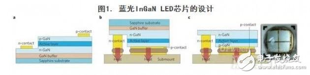
We are following the value of Win-win,innovation,responsibility and high efficiency to provide all clients high quality products and service. Welcome to contact us and visit our factory.