Correct wiring method for differential protection of three-coil transformers - News - Global IC Trade Starts Here Free Join
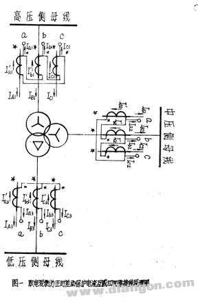
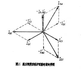
Differential protection plays a crucial role in transformer safety, and its wiring can significantly affect the system's performance. As agricultural electricity develops, many counties have built new 110 kV or higher voltage level substations, leading to the use of larger three-winding transformers. However, due to insufficient knowledge among some relay protection personnel about the correct wiring methods for these transformers, incorrect connections often occur, causing misoperations. This paper aims to provide guidance on the proper differential protection wiring for three-winding transformers. Most wiring errors in differential protection stem from mistakes in the current transformer (CT) circuit. The key to correct wiring lies in determining the polarity of the CT’s secondary winding. Since the secondary polarity is related to the primary, it is essential to first assume the primary polarity. Different regions may adopt different practices for this assumption, which can impact the final wiring configuration. A common practice is to assign the primary side of the CT as positive on the main power supply side. For example, if the high-voltage side is connected to the main busbar, it is considered positive, while the medium and low-voltage sides are assumed to be positive based on their respective transformer connections. This approach helps ensure accurate secondary polarity settings and correct differential protection wiring. Figure 1 illustrates the four-way CT connection for differential protection when all sides are assumed to be positive. The arrows indicate the direction of current flow, and the “☆†and “*†symbols mark the positive polarity ends of the primary and secondary windings, respectively. The wiring group used in this paper is Y/Y/△-12-11. As shown in Figure 1, the high-voltage side CT circuit is connected as a+→b-→b+→c-→c+→a-, forming a positive polarity loop. This method is equivalent to the Y/△-11 wiring of the transformer’s high-voltage winding. Similarly, the medium-voltage side CT is wired as a-→b+→b-→c+→c-→a+, representing a negative polarity loop that corresponds to the Y/△-5 wiring. Common mistakes often occur on the medium-voltage side. One frequent error is incorrectly connecting the CTs as if they were in reverse polarity, leading to phase mismatches in the differential circuit. Such errors can result in significant operational issues, including false trips. The low-voltage side CT is typically connected in a star configuration with a negative polarity outlet, corresponding to the Y/Y-6 wiring. This setup ensures that the phase relationship between the high and low sides remains consistent during normal operation. Correct wiring is critical to ensure reliable differential protection. While various methods exist, one recommended approach involves assuming the primary polarity on the busbar side rather than the main power supply side. This simplifies the wiring process and reduces the chance of errors. By following this method, the CT wiring becomes more intuitive and easier to remember, making it less prone to mistakes. Ultimately, the goal is to ensure that the differential protection system operates accurately and reliably under all conditions. Whether you're working with high, medium, or low-voltage sides, understanding the correct CT polarity and wiring sequence is essential for safe and efficient transformer protection.
Moving Generator Standard Specification:
Moving Generator,Mobile Generator,Mobile Generator Van,Trailer Type Generator Guangdong Superwatt Power Equipment Co., Ltd , https://www.swtgenset.com