Smart solutions in smartphone and tablet design
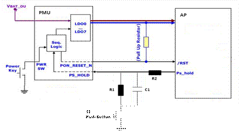
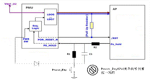
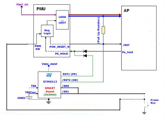
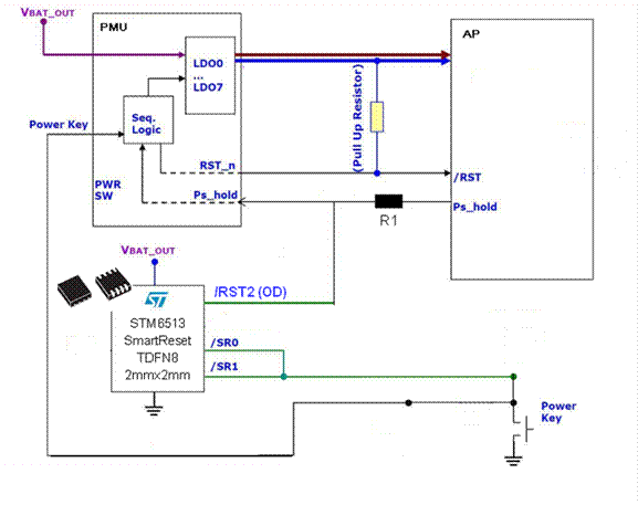
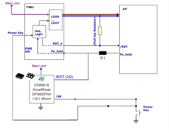
With the application of a large number of emerging data services, the power consumption of smartphones and tablets has increased significantly, resulting in a significant reduction in standby time. In order to extend the standby time, the design of the built-in battery has become more and more popular. This is because half of the volume lithium battery is occupied by its structure, if the battery built into the smart phone and tablet body, the lithium battery can save volume structure, thus greatly on the same or even greater volume Increase the capacity of the battery . As a result, the capacity of the battery has indeed increased dramatically, and a new problem has arisen. How can the system reset if the smartphone system and the tablet computer have a software system card machine during the application process? This article refers to the address: http:// Compared to the main function of the product, the mechanical reset device that releases the condition of the card is usually backward. To prevent accidental reset of the device, most manual reset buttons (if any) are hidden in the body. Since the reset button is difficult to reach, disassembling the battery becomes a very common solution. However, this approach not only makes the user less perceptible, but also increases the cost and can also damage the system, for example, to lose important data. So, how do you perform a hardware reset of your system in a smartphone and tablet with built-in battery design? This article introduces a hardware intelligent reset solution that not only enables intelligent reset of double-key long presses in smartphone and tablet design, but also enables popular one-button on/off and reset in smartphones and tablets. Smart solution. 2 Mechanisms and hidden dangers of on/off and reset of smartphone and tablet application platforms In today's smartphones and tablets mainstream platforms, often there is an application processor (Application Process / Baseband, hereinafter referred to as AP) plus power management chip (Power Management Unit, hereinafter referred to as PMU) architecture shown in Figure 1. Figure 1. Hardware architecture of AP PMU in smartphones and tablets In this hardware architecture, a power switch pin is provided on the PMU to be connected to a mechanical switch on the body (hereinafter referred to as Power_Key). When the mobile phone is in the power-off state, press Power_Key to pull the power switch pin of the PMU to the ground, which will start the PMU power-on process: the PMU starts the LDO to supply power to the AP, and sends a hardware reset signal to the AP. When the AP software system is started. After that, a PS_HOLD signal is sent back to pull the PS_HOLD pin of the PMU high, and it remains high during the working state; if the AP fails to raise the PS_HOLD pin for a certain period of time (Tpshold time), it indicates that the AP The startup fails, and the PMU automatically performs the power-off process. A relationship between the Power_Key and PS_HOLD signals is usually required, that is, the Power_Key signal must be kept low until the PS_HOLD signal is driven high by the AP, as shown in FIG. This is because if the AP power-on initialization fails and the PS_HOLD signal is not raised within the set time Tpshold, the Power_Key remains low to ensure that the PMU will be triggered to power up again, thus ensuring successful power-on. Figure 2. Timing relationship between PMU's Power_Key and PS_HOLD signals When the mobile phone is powered on, press Power_Key to pull the power switch pin of the PMU to the ground. The PMU will send an interrupt to the AP. The AP will respond according to the interrupt request, pull the PS_HOLD pin to the ground, and the PMU automatically powers down. process. In this mechanism, there is an obvious hidden danger: when the AP's system software card machine, it will not be able to respond to the power-off interrupt request sent by the PMU, and it will not be able to perform shutdown or reset operation. The possible solution is as follows: Set a button switch S1 at the PS_HOLD pin input of the PMU. When S1 is pressed, the PS_HOLD signal is pulled low to ground, triggering the power-off process of the PMU, as shown in Figure 3. Figure 3. Manual Reset Scheme in the Hardware Architecture of AP PMU This solution is certainly feasible, but it is necessary to hide the S1 in a small hole that is not easy to trigger. Usually, the user cannot touch the reset switch S1. In addition to the user's bad feelings and increased design costs and risks, there is still a problem with this solution - the current popular smartphone or tablet is designed with only one mechanical button, that is, the switch Power_Key connected to the PMU power switch pin. In this design, Power_Key and S1 cannot be set together. The reason is shown in Figure 4. Figure 4. Schematic diagram of the on/off button and reset button in the hardware architecture of the AP PMU. When the system is in the power-off state, if the Power_Key is short-pressed, the PMU will trigger the power-on process. When the AP power-on is completed, the PS_HOLD signal will be pulled high—the PS_HOLD of the PMU regardless of whether the button is pressed or released. Both can be pulled up in time during the Tpshold time through R2/C1/R1, and there is no problem in system power-on. When the system is in the working state, if the Power_Key is pressed, the PMU will enter the power-off process because the PS_HOLD signal is immediately pulled low. At the moment when the button is released, the system may be in a certain process of power-off or power-on process, which may lead to unpredictable results of possible shutdown and possible system reset. This is unacceptable for product design, as shown in Figure 5. Shown. More importantly, with this design, the system can not achieve software shutdown function at all. Therefore, in this circuit design, Power_Key and S1 cannot be set together. Figure 5. Timing of the on/off button and reset button in the hardware architecture of the AP PMU. In order to correct the PMU itself does not have a dedicated hardware reset input pin, but need to use the PS_HOLD signal to pull low to reset this defect, the new PMU began to introduce a special RESET_IN reset pin, allowing external circuits to reset through this pin hardware PMU. However, the problem still exists here is that the PMU specification requires that the on/off button and the reset button must be physically separated and cannot be set on the same button. The reset button needs to be hidden in the manhole on the body. A solution for single-button on/off and reset. So, is there a hardware solution that combines the on/off button and the reset button to achieve an intelligent solution for single-button on/off and reset in smartphone and tablet design? 3 One-button on/off and reset smart solutions in smartphone and tablet design The STMicroelectronics STM65xx family of intelligent reset chips has two or one inputs that can be connected to two or one function key on the device. If the two keys are held down simultaneously or by a single key for a certain period of time (the length of time can be set or selected according to the model), the reset chip will send a reset signal to the main processor. Reset the chip's two or one input and delay setting function, so that the "normal function" of the button and the "system reset function" of the button are combined into one, and the device can be effectively prevented from being accidentally reset. In the design of smart phones and tablets, the popular single-button on/off and reset design, that is, there is only one mechanical button on the whole body, which presses the functions of on/off and card reset. The STM6513 in the STM65xx Smart Reset Chip family is very successful in this function. The designer can connect the SR0 and SR1 input pins of the STM6513 to the Power_Key (you need to double-press and press the reset design, you only need to connect /SR0 and /SR1 to different function buttons), /RST2 Connected to the AP's reset input pin, and RST1 is connected to the PMU's PS_HOLD pin, which makes it easy to implement single-button on/off and reset smart solutions in smartphone and tablet designs, as shown in Figure 6. Option 1. Figure 6. Smart solution with single-button on/off and reset of STM6513 When the system is powered off, if the Power_Key is short-pressed, the PMU will trigger the power-on process. When the AP is powered on, the PS_HOLD signal will be pulled high. There is no problem with the system being powered on successfully. Since the Power_Key is short pressed in the design, it does not trigger the delay reset function of the STM6513 (optional, for example, 8 seconds). When the system is in the working state, if Power_Key is pressed for more than one time (optional, for example, 8 seconds), /RST2 outputs an active low reset signal to the AP, and the RST1 pin outputs a high level signal. . Due to the existence of the line and function circuit of the two diodes on the PS_HOLD input pin of the PMU, the RST1 output of the STM6513 will remain high when the AP is reset (the trec of RST1 can be passed through the external capacitor pin of the STM6513 as needed). Make settings) until the AP drives the PS_HOLD pin high. In this way, when the system is reset, only the AP is reset by the STM6513, and the PMU does not actually power off, which ensures that the system reset is successful. In addition, since the PMU is not powered off during system reset, the cached data is not lost, and the user application data can be saved when the computer is dead. Some designers may prefer to be able to restart the PMU during a system reboot. For this type of designer, you can also use the /RST2 pin of the STM6513 to connect to the PS_HOLD pin of the PMU (for the PMU with RESET_IN, it can be connected to the RESET_IN pin), as shown in Figure 2 of Figure 7. When the system is in the power-on state, if Power_Key is pressed for more than one time (optional, for example, 8 seconds), /RST2 outputs an active-low reset signal to pull the PMU's PS_HOLD signal low. Since the trec of /RST2 is fixed (for example, 210ms), that is, /RST2 will become the output high-impedance state after the reset signal is kept low for 210ms, thus releasing the PS_HOLD signal of the PMU, and the PS_HOLD of the PMU will be completely Controlled by the state of the AP's PS_HOLD output pin. Since the Power_Key is still low at this time, the PMU will be triggered to power up again, and the power is successfully turned on. Figure 7. Smart solution with single-button on/off and reset of STM6513 2 For the designer using Option 2, a more cost-effective solution is to use STMicroelectronics' new STM6519 chip, which is a one-button delay reset chip. The reset delay time is selected by model, and only one /RST reset output signal. It is packaged in UDFN6 or UDFN4 1.0x1.45mm, as shown in Figure 8. Figure 8. Smart solution with single-button on/off and reset of STM6519 With the STMicroelectronics STM6513 or STM6519 smart reset products, the following single-button on/off and system reset processes can be implemented: In the off state, short press, power on; In the booting state, under the premise that the AP system software does not have a card machine, the short button, the AP correspondingly displays “Return? Shutdown?†on the display for the user to select – if the confirmation returns, return; if the shutdown is confirmed, the AP Pull PS_HOLD low, PMU enters the power-off process, and finally shuts down. In the case of the AP system software card machine, a long button (optional, for example, 8 seconds), the system performs a hardware reset and restarts the boot. 4 Summary This paper first introduces the reset mechanism and hidden dangers of the APPMU hardware architecture on the smartphone and tablet platforms, and then describes the use of STMicroelectronics STM6513 and STM6519 smart reset chips to achieve double-button long-press reset, especially on smartphones and tablets. A smart solution for single-button on/off and reset in the computer. STMicroelectronics' STM65xx smart reset chip family enables product designers to remove traditional reset keys and access holes that hide reset keys on the body, saving cost, design risk, and user satisfaction. Three-Axis Micro DSLR Stabilizer is composed of pan axis, rolling axis and tilt-axis. With a gyro-stabilized gimbal system, it keeps stabilized or steerable horizon with automatic calibration to give you an unprecedented smooth shooting experience.
5. After-sales service, solve within 3 working dates.
Three-axis Micro DSLR Stabilizer Three-Axis Micro DSLR Stabilizer,Popular Three-Axis Micro DSLR Stabilizer,Professional Three-Axis Micro DSLR Stabilizer,Handheld Three-Axis Micro DSLR Stabilizer GUANGZHOU WEWOW ELECTRONIC CO., LTD. , https://www.stabilizers.pl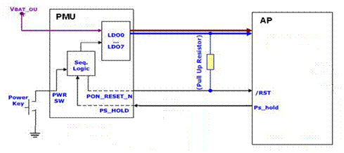


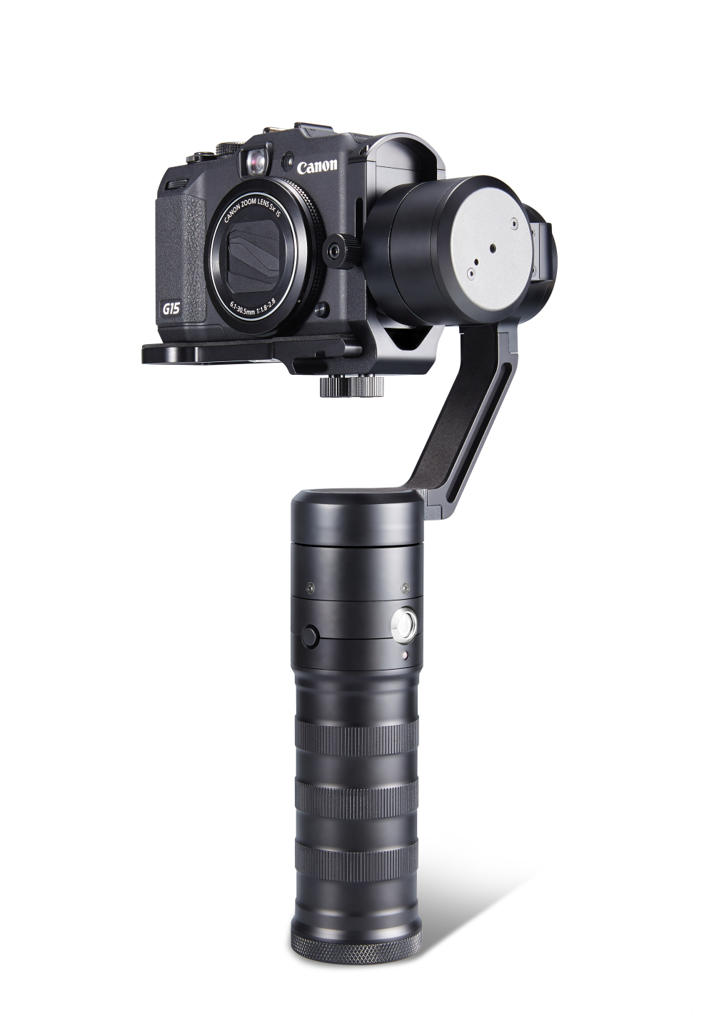
Wewow focusing on handheld stabilizer is a technology company which does R & D independently. With Wenpod series product released, the company achieved the industry's praise and quickly became the leader of the smart stabilizer industry.
Our service
1. Reply to you within 24 hours.
2. Already sample: within 1-2days.
3. Shipping date: within 24 hours once get the payment.
4. 12 months warranty.
Wewow appreciates domestic and international business relationship!