TMS570 MCU enhances the safety of automotive brake systems
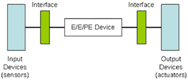
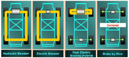
Summary This article refers to the address: http:// A microprocessor (MCU) is a key component in an ECU. It is not possible to meet SIL3 certification requirements using a traditional automotive MCU. A new chip architecture is required to ensure processing results, data integrity of bus traffic, and data security and reliability in memory while meeting stringent response time requirements. Developers can take advantage of commercially available microprocessors to provide the technology needed to achieve SIL3 certification standards for ECU brake control functions. One such microprocessor is the TMS570 developed by TI in collaboration with Robert Bosch GmbH. Electronic chassis management technology is extremely attractive for any major automotive system function, but for a variety of reasons, the technology is difficult to achieve, not to mention the many challenges in terms of safety and reliability. However, in response to current security challenge requirements, the International Electrotechnical Commission (IEC) has defined standards for the functional safety of electrical/electronic/programmable electronic safety-related systems. Currently, IEC 61508 is considered the most advanced standard in the development of safety-critical systems. Although the standard has not yet been fully enforced in the form of law, it is hoped that automotive system designers will be able to meet this practical technical standard. Automotive system designers must consider the requirements of the entire signal chain, from input sensors to digital processing and transmissions, while building the functional safety of the application. Figure 1. The functional security of the overall system relies on the device to function properly in response to input. IEC 61508 defines “danger†and “risk analysis†as part of the system design and defines the “functional safety†of the Electronic Control Unit as “part of the overall safety†– depending on whether the system or equipment can Correct response to its input." Each security function of the system is evaluated based on “requirements†(what is required for the function) and “integrity†(the possibility to successfully perform the function). In addition, the standard further divides the probability of dangerous failures of safety functions in high-intensity or continuous operation modes into four different Safety Integrity Levels (SILs). Each level covers a range of acceptable failure rates, known as Mean Time Between Failure (MTTF), and SIL4 is the most stringent of these. The SIL rating applies to many industries, including the automotive industry, and the definition of each SIL rating applies to the respective industry sector. SIL2 and SIL3 in the Safety Integrity Level are the most common safety levels in non-road applications. Depending on the safety function and importance, the automotive system can comply with the SIL2 or SIL3 regulations of the IEC 61508 standard. The reliability of the self-test system requires that the “safety failure factor†(SFF) obtained by multi-level statistics reaches 99%. The specific calculation method of the reliability parameter is the ratio of the detected dangerous fault (including non-hazardous fault) to all faults. “Diagnostic Coverage†(DC) is the ratio of detected dangerous faults to all dangerous faults. In addition, DC should reach 99% for safety-critical automotive systems. The ability to pass SIL3 certification for automotive systems usually depends on the performance of the electronic control unit (ECU) that initiates and controls the mechanical system. Independent safety assessment agencies such as TÜV Rheinland are responsible for ECU evaluation and SIL3 certification for automotive systems. TÜV is an international service group that issues safety and quality certificates for products, systems and services. Mission-critical integrated mechanical systems, such as brakes, are not completely replaced by electronics. However, any advanced mechanical or electronic safety required for SIL3 certification is achieved through the use of redundant systems that facilitate widespread implementation of redundancy. SIL3 certification for electronic subsystems Replacing hydraulic or mechanical systems with electronic systems will inevitably benefit OEMs, automakers and consumers. Electronic systems eliminate the belt drive burden of internal combustion engines, helping to reduce cost, weight and fuel consumption. Automakers can replace the hydraulic brake booster with a mechanical solution and eventually eliminate the hydraulic drive system completely, enabling a fully electronically controlled line control system. However, this revolutionary transformation requires the implementation of redundant or backup systems (similar to avionics systems) to avoid the risk that the vehicle may lose complete braking capability at a dangerous time. The excessive steps during the period include the "hybrid brake" mode, that is, the hydraulic backup system can be installed only on one of the vehicle instead of the two axles. Figure 2. Although the fully electronically controlled line control system is still in development, replacing the hydraulic booster with an electrical solution can significantly reduce fuel consumption, cost and noise. A microprocessor (MCU) is a key component in an ECU. SIL3 certification requirements are not possible with traditional automotive MCUs. A new chip architecture is required to ensure processing results, data integrity of bus traffic, and data security and reliability in memory while meeting stringent response time requirements. According to the IEC 61508 standard, the causes of dangerous faults include the following factors: -- Software or hardware system specification is incorrect - Missing safety requirements specification —— Hardware random failure —— system cause failure -- human error —— Environmental impact (EMI, temperature, machinery, etc.) From a complete system perspective, hazard assessment and safety integrity requirements include the following factors: Ensure stable power supply and clock signal integrity in the case of voltage drops, false signals, etc. Redundancy or authenticity checks for processing and communication, including signals to and from sensors and actuators; Provide fault detection function; Provide fault management strategies, including defining security status and fault protection in the case of fault tolerant architecture, emergency operating mode, and controllable system shutdown; Enhanced software development processes include the use of formal specifications, a subset of programming languages, and code verification tools. Strong support for silicon chips Developers can take advantage of commercially available microprocessors to provide the technology needed to achieve SIL3 certification standards for ECU brake control functions. One such microprocessor is the TMS570 developed by TI in collaboration with Robert Bosch GmbH. In silicon chip design, chip layout itself is a big challenge and should include proprietary intellectual property (IP) to reduce and detect random hardware and system cause failures. In addition, we can compare the processing results with a dual-core processor architecture running in lock-step mode, thereby avoiding a lot of time developing separate checker microprocessor software. To protect the memory subsystem from external events, we should implement error correction code (ECC) and parity protection on the main and local memory and bus traffic. To simplify development, developers should also use devices from the MCU that have implemented the FlexRayTM network protocol. This deterministic communication standard developed by leading automotive manufacturers and suppliers provides comprehensive deterministic redundant communications for advanced automotive systems. For example, TI's TMS570 MCU is a symmetric dual-core MCU based on two identical next-generation ARM® R4 CortexTM cores. Each Cortex-R4 core delivers 300 MIPS performance, and the TMS570 integrates 2MB of on-chip flash, FlexRayTM networking, BIST, CAN, and a variety of peripherals. The dual core is tightly coupled to the patent-pending architecture for maximum reliability. Advantages of the Cortex-R4 The Cortex-R4's 64-bit AMBA 3 AXI memory interface offers several key performance benefits that enhance reliability, including issuing multiple pending addresses and supporting out-of-order data returns. Perhaps the most significant advantage is that even if the memory or peripherals are slow, it does not block the bus, which in turn affects access speed. This feature allows the kernel to perform more access without having to wait for slower access completion. In addition, the 64-bit wide bus increases the available bandwidth, allowing cache line fills to be completed with just four accesses, unlike the ARM946E-S. Compared to the 946E-S, the Cortex-R4 also significantly improves the interrupt latency, and the worst-case interrupt latency and average interrupt latency are improved. For example, the 946E-S must wait for the instruction or interrupt process to complete, but not to give up halfway. In the worst case, it means that even with zero wait state memory, the interrupt latency can be as long as 118 cycles. Although the above situation is unlikely to occur frequently, real-time systems must do this worst. On the other hand, if an interrupt request is received during execution, the Cortex-R4 processor will relinquish the multi-load instruction of normal memory. The TMS570 MCU is designed to control the longest interrupt latency to around 20 cycles, with little or no access to the AMBA AXI memory and peripheral access times. In addition, the Cortex-R4 processor provides a non-maskable interrupt option to prevent software from disabling fast interrupt request (FIQ), which is especially important for safety-critical applications. in conclusion For automakers and OEMs, as vehicles become more complex and integrated, more and more features are becoming more important. Innovative designs incorporating the Cortex R4 core, such as the TMS570 device, enable fault detection and response times as required by the IEC 61508 standard. Incorporating the reliability of microprocessor-based systems into the SIL3 certification category marks a major step forward for automotive OEMs and automakers in the full implementation of vehicle-driven drive functions. The TMS570 MCU is a SIL3 certified 32-bit microprocessor family that meets the braking requirements and will be implemented in the 2008 model year. The technology development strategy of the TMS570 MCU covers electronic stability control, chassis control and steering systems. Antenk coin cell battery retainers Designed for memory back-up and stand-by applications, these contacts permit quick and easy coin cell replacement and installation. Eliminating "soldered-in" cells, computer, video, telecommunication and similar PCB based product users now have a reliable, "no tools required" method for changing batteries.
Extremely economical, these retainer contacts are available in surface mount (SMT) or thru hole mount (THM) styles for 4.8mm, 6.8mm, 11.6mm,12mm, 16mm, 20mm, 23mm and 24mm coin cells. The THM version has stable mounting legs for excellent board retention during wave solder. The SMT version includes a unique solder tail "flow-hole" design to bolster reflow and strengthen solder joints. They are manufactured from phosphor bronze, precision stamped and are plated with either a high luster nickel finish or matte tin finish ideal for low temperature soldering enviornments. Both feature dual spring contacts to assure reliable connections and a low contact resistance.
Antenk Coin/Button Cell-retainers And Contacts
Coin Cell, Button Cell, Retainers, Contacts
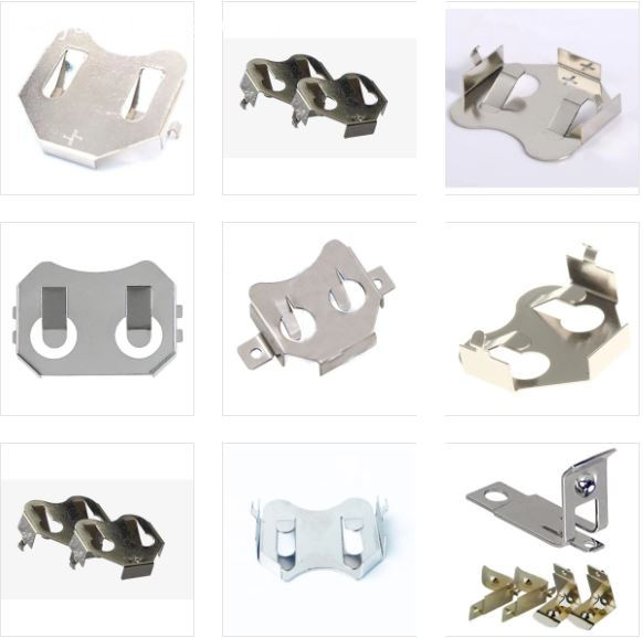
Designed for memory backup and standby applications, Antenk's compact coin cell battery retainers permit quick and easy coin cell replacement and installation. By eliminating soldered-in cells, computer, video, telecommunication, and similar PCB based product users now have a reliable, no tools required method for changing batteries.
These holders and retainers are available in surface-mount (SMT) or through-hole-mount (THM) styles for 4.8 mm to 24 mm coin cells. The THM version has stable mounting legs for excellent board retention during wave soldering. The SMT version includes a unique solder tail flow-holedesign to bolster reflow and strengthen solder joints. Both feature dual spring contacts to assure reliable connections and low contact resistance.
Coin Cell Retainers by Size of Cell Coin/Button Cell-retainers And Contacts Button Contacts,Coin Cell Retainers And Contacts,Coin Cell Retainers ShenZhen Antenk Electronics Co,Ltd , http://www.antenk.com


Coin Cell Retainers are simple metal contacts that both electrically connect coin cells and hold them in place, while taking up minimal additional space on the PCB. They feature nickel-plating, and since most coin cells have nickel shells this helps to prevent galvanic corrosion, an electrochemical process that can damage dissimilar metals that are in electrical contact. Our retainers are always designed with automation in mind, and can be easily picked and placed, with both through hole and surface mount retainers available for most coin cell sizes. Combining the ease of automation with the low cost of Antenk's retainers, it is no wonder they are such a popular product.
Coin Cell, Button Cell, Retainers, Contacts Features
Available in THM or SMT configurations
SMT solder tail with flow-hole design for increased joint strength
SMT solder tail located outside of retainer body which facilitates visual inspection of the solder joints
THM legs maintain relative position during and after soldering
Reliable spring tension assures low contact resistance
Retains battery securely to withstand shock and vibration
Ideally suited for high-density packaging
Ideal for low-profile space-saving PCB applications
Designed for reflow and all PCB soldering applications
Compatible with all wave and reflow operations
Compatible with most vacuum and mechanical, pick and place assembly systems
Matte-tin plate for lower soldering temperatures ideal where other temperature sensitive components are being used
Tin-nickel plated retainers are ideal for lead-free, high-temperature soldering applications
Retainers available for coin cell batteries from 4.8 mm to 24 mm diameter
191 | 335 | CR1025 | CR1216 | CR1220 | CR1225 | CR1632 | CR2016 | CR2032 | CR2320 | CR2325 | CR2330 | CR2354 | CR2430 | CR2450 | CR2477 | F3 iButton | F5 iButton | LR1120 | LR44 | ML414 | SR512SW | SR60 | V80H or CP1654 | BR1025 | BR1216 | BR1220 | BR1225 | BR1632 | BR2016 | BR2032 | BR2320 | BR2325 | BR2330 | BR2450 | BR2477 | Other Sizes