Interconnected automotive 48V and 12V power rails in a dual battery system
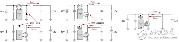
The electrification of the automotive industry is growing at a growing rate, with the main driver coming from government-issued carbon dioxide (CO2) emission reduction standards. The EU's goal is to achieve a new car emissions of only 95g/km by 2020. Other countries such as China are also developing similar regulations. To meet these standards, automakers are developing lightweight hybrid electric vehicles that use secondary high-voltage batteries and standard 12V automotive batteries. German car manufacturers have begun to define and build systems based on 48V batteries. At lower currents than traditional 12V batteries, the 48V battery provides more power while saving wire harness weight without compromising performance. In this development process, the LV148 standard has become the main starting point for dual-battery automotive systems. The top block diagram of the dual battery system is shown in Figure 1. Figure 1: Block diagram of a dual battery automotive system What are the challenges of the proposed system? How to overcome obstacles? Many OEM systems require that energy must be transferred from a 48V track to a 12V track and vice versa. If the battery is discharged, bidirectional power transfer is required to charge the battery and provide additional power to the opposite voltage rail under overload conditions. In order to charge the battery without damaging the battery, the controller must be able to control the charging current very accurately. In most automotive applications, the maximum power transfer is not low, typically in the range of 2 kW to 3 kW. The voltage variations across the two tracks can be large. According to the LV 148 specification, a 48V supply rail is typically between 36V and 52V, while a 12V supply rail can be in the 6V to 16V range. The protection circuit must also be present for any fault conditions that could damage the system. With these requirements, it is clear that the DC/DC converter required to bridge the 48V and 12V rails is not a simple design project. The design complexity is greatly reduced by the fact that the voltage range of the 48V power rail and the 12V power rail does not overlap. For power transfer from a 48V rail to a 12V rail, a buck converter can be used, and a boost converter can be used to transfer power from 12V to 48V rail. Due to kilowatt power requirements, each converter should use a synchronous MOSFET instead of a freewheeling diode to increase system efficiency. Buck and boost topologies are well known in power electronics, but designing two separate converters will take up valuable board space and increase system complexity and cost. A closer look at the two topologies shows that the power chains of the buck and boost converters are very similar. The two topologies consist of at least two power MOSFETs, one inductor and a certain amount of output capacitance. The difference between topologies is the controller. In a buck topology, the controlled switch is a high-side MOSFET; in a boost topology, it is a low-side MOSFET. By simply changing the controlled switch, assuming you have chosen the right controller, you can change the direction of current flow in the inductor while using the same power train components. Figure 2 shows the evolution from two converter solutions to a single converter solution. Figure 2: Evolution of a single-controller bidirectional converter Although the synchronous switch is necessary for high current design, it is not effective for all obstacles. At 2 kW, the 12V rail will turn on approximately 166A. A quick look at the content, you will find that you will need multi-phase operation to implement this design in practice. By using a multiphase architecture, you can reduce the physical size of components and make thermal management easier. To make it easier to parallel each supply phase, the control scheme in buck or boost mode operation should be current mode control. Multiphase operation also allows for interleaved switching of each phase. Switching each phase at each time reduces output ripple, which in turn helps reduce electromagnetic interference (EMI). In all systems, you must design a protection circuit for operator safety. Common protection features such as undervoltage lockout (UVLO) and overvoltage protection (OVP) ensure that the battery does not charge too much or overcharge. The peak inductor current limit helps prevent excessive stress on each supply phase and saturates the inductor. In a two-battery car setup, a circuit breaker is also required to disconnect any electrical connections between the 48V and 12V rails. Monitoring circuitry can also help extend security features. For example, during energy transfer, monitoring the current in each channel can indicate if or when a fault condition has occurred. Digitally controlled DC/DC converters are a possible solution, but there are several major drawbacks to this approach. First, a large number of discrete components are required: current sense amplifiers for each phase, power MOSFET gate drivers, protection circuits, and supervisory circuits. Each component will take up valuable space on the printed circuit board (PCB). Second, a high-end microcontroller is required to implement the converter's current and voltage control loops. Third, the microcontroller also introduces a delay in the protection circuit, which can cause catastrophic damage at high power levels. Fourth, the design cycle for digital control can be on the order of a few years. You must have an in-depth understanding of switching power supplies and digital controls. That being said, there are some additional advantages. From a system level perspective, digital control can be more flexible, allowing control scheme parameters and regulating dynamic changes in voltage. Sharing information with other subsystems can improve overall system performance. TI's LM5170-Q1 synchronous dual-phase bidirectional buck/boost controller solves many of these challenges. Integrated current sense amplifiers, high current gate drivers and system protection features, including integrated circuit breakers and channel current monitoring, eliminate many of the discrete components required in digital solutions. Stacking multiple controllers in parallel delivers kilowatts of power while optimizing the control of the current-charged battery with the LM5170-Q1's proprietary average current mode control scheme. Read the blog post "Selecting a Bidirectional Converter Control Scheme" to see how TI's average current mode control method compares to a conventional control scheme. Bridging 48V batteries and 12V batteries is complicated, but it is possible to implement each step carefully. A dramatically more leakproof system. geekvape wenax series box,geekvape wenax series replacement pods,geekvape wenax series mods,geekvape wenax series kit,geekvape wenax series pod kit Ningbo Autrends International Trade Co.,Ltd. , https://www.vapee-cigarettes.com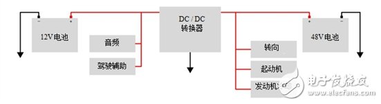
A cartridge so durable, every droplet has nowhere to go.
With a huge leap in battery life with 1000mAh, enjoy a 2-day vape.
New mesh coil, tight and smooth MTL.
All for an enduring vape.
Prevent overheating accidents by pressing the button five times.
After the LED flashes in white, blue, and green in a row, Wenax H1 is
safe to go.
Enjoy three different output levels by simply pressing the firing
button three times.
The LED will indicate the status of the battery and the output
level. All operations are within one button.