Differential Amplifier AD813x FAQ
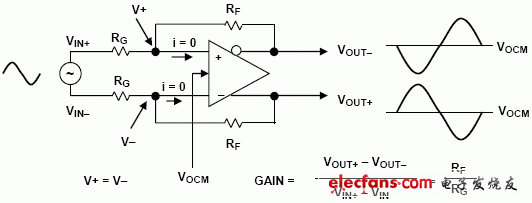
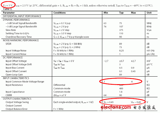
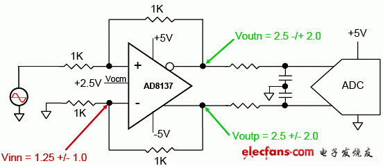
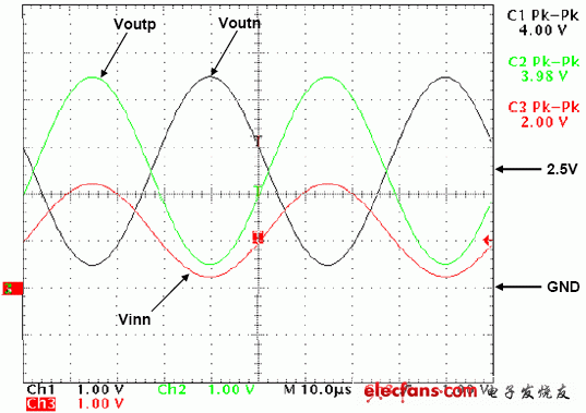
Question: How do I calculate the gain of a differential amplifier circuit and how do I analyze the differential amplifier circuit? Answer: As shown in the figure, the basic principle of differential amplifying circuit analysis is the same as that of ordinary operational amplifiers, and it also has its own unique analytical principles: Differential amplifier circuit analysis diagram 1. The current at the inverting input is zero, which is the principle of virtual disconnection. 2. The voltage at the same inverting input is the same, that is, the principle of virtual short. 3. The output differential signals have the same amplitude, 180 degrees out of phase, and are symmetric about the Vocm common mode voltage. 4. According to the above three principles, the gain of the differential signal is Gain=RF/RG. Question: Why is the output of the circuit incorrect? Answer: For the application of differential amplifiers, to get the correct output, you must pay attention to the following points: 1. The swing of the output signal must be within the range specified in the data sheet. Taking the AD8137 as an example, in the case of a single power supply of 5V, both Vout- and Vout+ must be within 450mV to 4.55V (see table below). 2. The range of the input signal must be within the range specified in the data sheet. Taking the AD8137 as an example, in the case of a single power supply of 5V, the voltages of +IN and -IN must be within 1 to 4V. (see table below) Data sheet single power supply 5V power supply chip indicator In your circuit, you must first perform an analysis and check to see if the voltage at the output and the range of the common-mode signal at the input are within the range specified in the data sheet (note the condition of the supply voltage). In the case of a single power supply, problems are more likely to occur. Below we use AD8137 to illustrate how to judge whether the circuit can work normally? As shown in the figure, this is an amplifier circuit of the AD8137 with +/-5V power supply. The input is a 8Vpp signal. According to the principle of virtual short and imaginary, according to the analysis of 2.1, the differential signal gain is 1, that is, the swing of each end of the differential output is +/- 2V, but the phase is 180 degrees out of phase. Since Vocm incorporates a common mode voltage of 2.5V, the voltages of Voutp and Voutn are 2.5V +/- 2.0 V and 2.5V-/+2.0V, which is in the range of 0.5V to 4.5V. This signal range is in accordance with the data sheet's +/-5V power supply (-4.55V~+4.55V). Then we calculate the common mode voltage at the input. According to the principle of virtual short and virtual break, the voltage of Vinn is the midpoint of Voutp above the two 1K ohm resistors, that is, the common mode voltage shown in red is Vinn= 1.25V +/-1.0V, which is 0.25V~2.25V, which also meets the input common-mode voltage requirements (-4V~+4V) in the data sheet of +/-5V power supply. So this circuit meets the requirements and will work correctly. The figure below is the waveform of each point.
The Work Light is Ideal for mechanic's, DIY, boating, camping, night fishing ,Camping, Hiking, Workshop, Roadside safety, Auto repair, Emergency kits, Survival device, Home security etc.
Work Light Work Lights,Extendable Work Light,Rotating Work Light,Switch Light Ningbo Henglang Import & Export Co.,Ltd , https://www.odistarflashlight.com


AD8137 dual power supply amplifier circuit 
AD8137 dual power supply circuit waveform at each point
Both Work Light's Base and Body have strong magnet to magnetize on metal surfaces for more convenience; Use Hook to hang on any place to provide brightness.
The Opereating Time of work light up to 6 Hours As Per One Fully Charged, It can Also be Used as a Backup Battery to Charge Your Phone or Other Digital Device.