48v to 12v simple circuit diagram (five 48v to 12v simple circuit design schematic diagram)
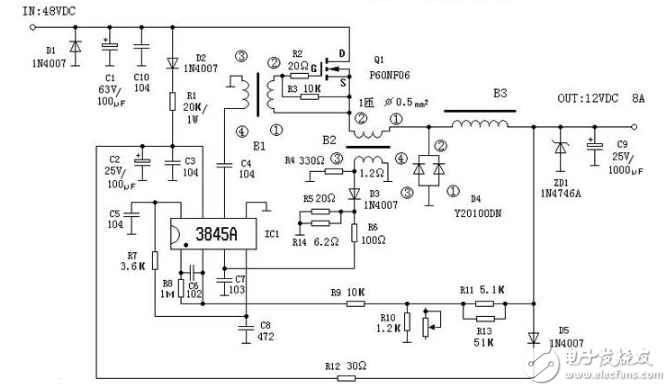
This circuit is based on physical analysis and operates as a DC-DC converter. The power supply provides approximately +12V to IC1 through D2 and R1. The output pulse from pin 6 drives Q1 to oscillate after coupling with C4 and the transformer. When Q1 is turned on, the current flows through L filter and C9, providing power to the load. When Q1 is off, the magnetic energy stored in the transformer-type inductor B3 is converted into electrical energy. This energy is then delivered to the load via the free-wheeling diode D4, ensuring continuous power delivery. As a result, the load receives a smooth DC voltage.
If the output voltage becomes too low or too high, a sampling voltage is taken from a resistor divider consisting of R11, R10, and R9. This voltage is sent to pin 12 of IC1, where it is compared with an internal 2.5V reference voltage. This comparison controls the conduction pulse width of Q1, stabilizing the output voltage. In case of a short circuit or when the load current exceeds 8A, the voltage at pin 13 of IC1 rises, which reduces the pulse width and turns off Q1, protecting the transistor from damage.
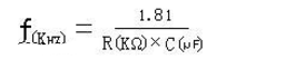
C8 and R7 form the oscillation time constant, setting the operating frequency of the circuit to 65kHz. The formula for calculating this frequency is shown below:
The internal structure and pin functions of the 3845 are illustrated below:
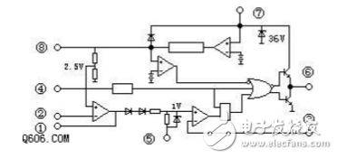
Pin 1: Error amplifier output / compensation. Pin 2: Voltage feedback input. Pin 3: Current sensing input. Pin 4: Oscillator time constant. Pin 5: Ground. Pin 6: Switching driver output. Pin 7: Power supply. Pin 8: 5V reference voltage, typically connected to the oscillator.
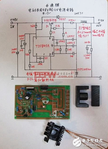
This circuit is used in electric vehicles and converts 48V to 12V. The input voltage range is between 36V and 48V, and the maximum current can reach up to 10A. The schematic is shown below:
Computer Case, Desktop Computer Case, Console Case,Gaming Computer Case,Boluo Xurong Electronics Co., Ltd.
Boluo Xurong Electronics Co., Ltd. , https://www.greenleaf-pc.com